by Michael Cropper | Jan 9, 2023 | IT, Technical |
This is a topic that comes up quite infrequently for many people and for most, never. It’s also one of the topics that is significantly more complex than it should be and one that is fairly poorly documented online about how to do this properly. Fundamentally this is a basic Copy & Paste exercise at best, but it’s made ridiculously complex by the underlying technical gubbins. So hopefully this blog post can clear up the steps involved and some of the considerations you need to make.
Old and New Disks
Disks come in many different shapes and sizes both conceptually and physically, with varying connectors and different underlying technologies. The nuances of these are beyond the scope of this blog post, but to put a few basics down to help conversation let’s look at a few of these at a high level.
We’ve previously covered off topics on the Performance of SSDs VS HDDs so take a look at that for some handy background info.
Summary being that you essentially have two types of hard drives;
- Mechanical Hard Disk Drive (HDD) – Has moving parts
- Solid State Drives (SSD) – Has no moving parts
See the above blog post for further insights into the differences.
Anyhow, the important point being for the purpose of cloning a hard disk is that you need to know the details of what you are going from and what you are moving to. Get this wrong and you can seriously mess things up in a completely un-recoverable way, so please be careful and if you aren’t sure what you are doing, don’t proceed and instead pass this onto a professional to do this for you.
Disk Connectors – IDE VS SATA
For the sake of simplicity, the two core connectors for disk drives fundamentally fall into either IDE (old) and SATA (new). Yes, the teckies who are reading this will say that this is garbage, and it is. But, in reality, for those reading this blog post, this is likely going to cover 99% of the use case.
In reality there are many types of disk connectors from PATA, SATA, SCSI, SSD, HDD, IDE, M.2 NVMe. M.2 SATA, mSATA, RAID, Host Bus Adapters (HBA) and more (and yes, not all of these are technically connectors… but for the sake of simplicity, we don’t care for this blog post). At the time of writing, the majority of people using the many other various types of disk connectors outside of the basics are generally going to be working within corporate enterprises which tend to operate on a bin and replace mentality from a hardware perspective for basic user computers and for data centres and server racks have setup with cloud native data storage with high availability and lots of redundancy. For many smaller organisations and/or personal use case, this is a goal to work towards.
Which is why we are covering this topic for the average user to help to understand the basics for how to clone a hard disk either if you are upgrading and/or are trying to recover data from a failing disk.
Adapters
Ok, so we’ve covered off the different types of hard disks, it’s time to look at how we connect them to a computer to perform the data migration. Here is where we need the correct connectors to do the job, and this isn’t straight forward.
For simplicity and ease, USB is likely to be the easiest solution for the majority of use cases. Note there is a significant difference in USB 1.0 VS USB 2.0 VS USB 3.0 when it comes to performance and to add to the complexity, there are also different USB Form Factors (aka. different shapes of the connector, but fundamentally doing the same thing) which adds to the confusion.
I work in this field, and I am continually surprised (aka. annoyed…) by the manufacturers who continually make this 1000x more complex than it needs to be. I for one am extremely happy that the European Union (EU) has decided to take a first stance on this topic to help to simplify the needless complexity by standardising on a single port type for charging devices. Personally I have endless converters, adapters, port changers, extender cables and more for the most basic of tasks. It’s a bloody nightmare on a personal level. And at an environmental level, just utterly wasteful.
Anyhow, to keep things simple again, there are a few basic adapters you probably need to help you with cloning a hard disk. These are;
- USB External SATA Disk Drive Connector / Adapter Cable (buy here)
- USB External SATA, 3.5” IDE, 2.5” IDE Disk Drive Adapter Tool Kit (buy here)
Connectors, Adapters and Speed
This is a complex topic, and one that quite frankly I don’t have the time to get into the details of – mainly because the manufacturers don’t make this easy and/or make this far more difficult than it should be. You see, we have things such as USB 1, 2, 3, SATA 1, 2, 3, IDE, 1, 2, 3 etc. and I just don’t have the mental capacity to care about too much the differences between these things. I work with what is available and adapt as needed.
The reality is that each and every connector or adapter has a maximum data transfer rate based on the physical materials and hardware that the device has been manufactured from. Everything has limitations and manufacturers don’t make this info easily accessible and/or understandable to the average joe.
Unique IDs of Disk Drives
Right, so now we’re onto the actual hard disk data migration. Now things get fun, and possibly dangerous – so be careful.
Almost every guide I’ve read online skims over this really important point, and it’s probably the most crucial point to take into account – which is to know your IDs, your Unique Hardware Identifier.
For a bit of background as it’s important to understand. For those with a software engineering and/or database background, you will be very familiar with a Unique Identifier for a ‘thing’. Well, with hardware manufacturing, they also do the same thing. For every physical chip that is manufactured, this is generally embedded with a hard coded unique identifier which both helps, and hinders, in many different ways, but that is a topic for another discussion. For example, the sensors that we use on the GeezerCloud product have a Unique ID for every single sensor that we use.
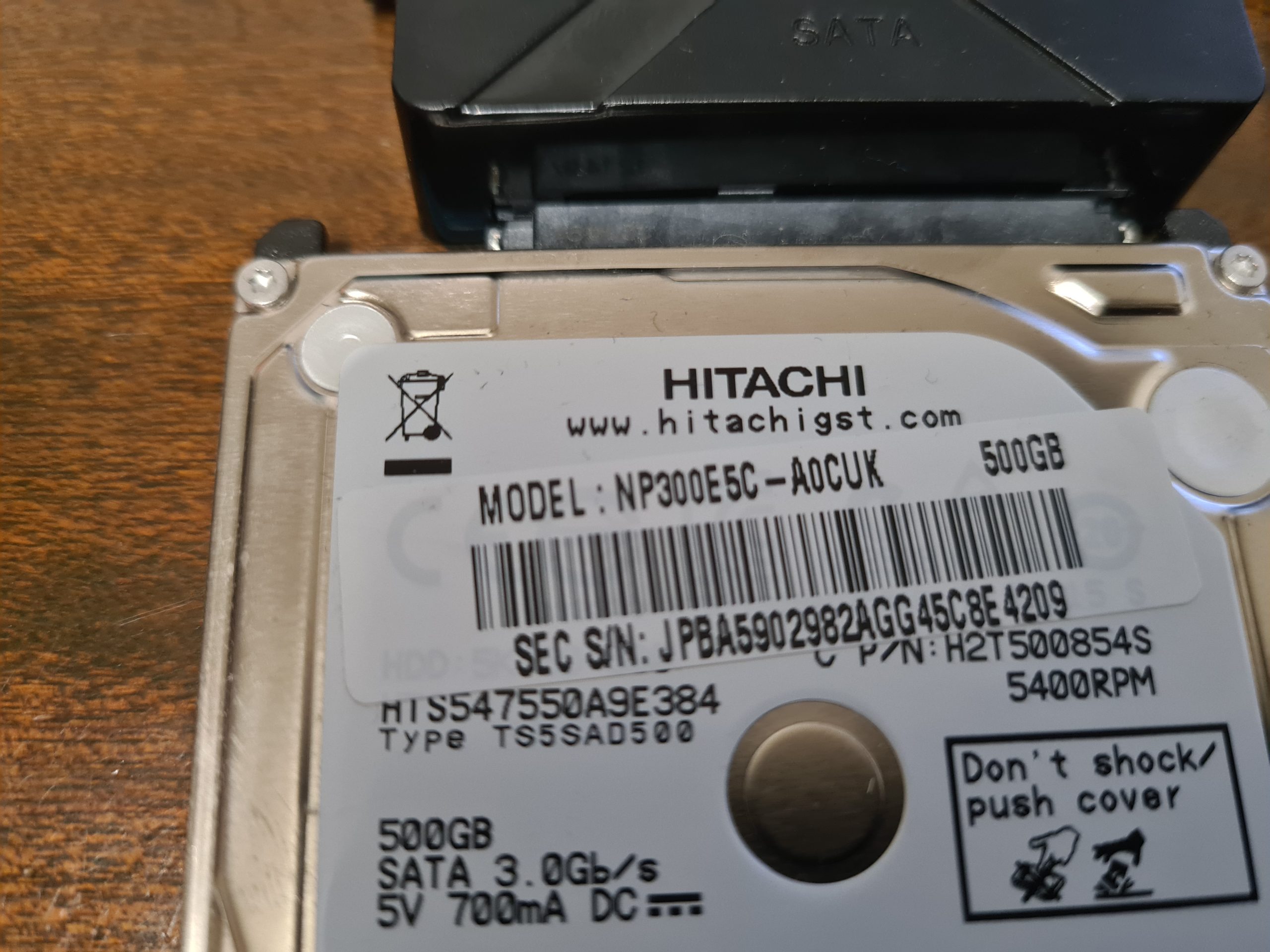
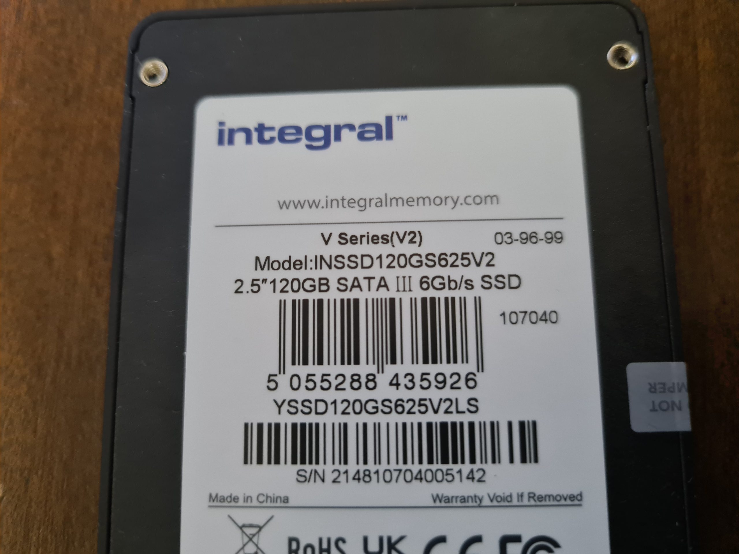
Anyhow, the most important aspect of what I want to mention for this blog post is that all disk drives have a unique identifier. Thankfully this identifier is printed on the physical disk that you have in front of you. It’s printed on the sticker that is physically attached to the disk.
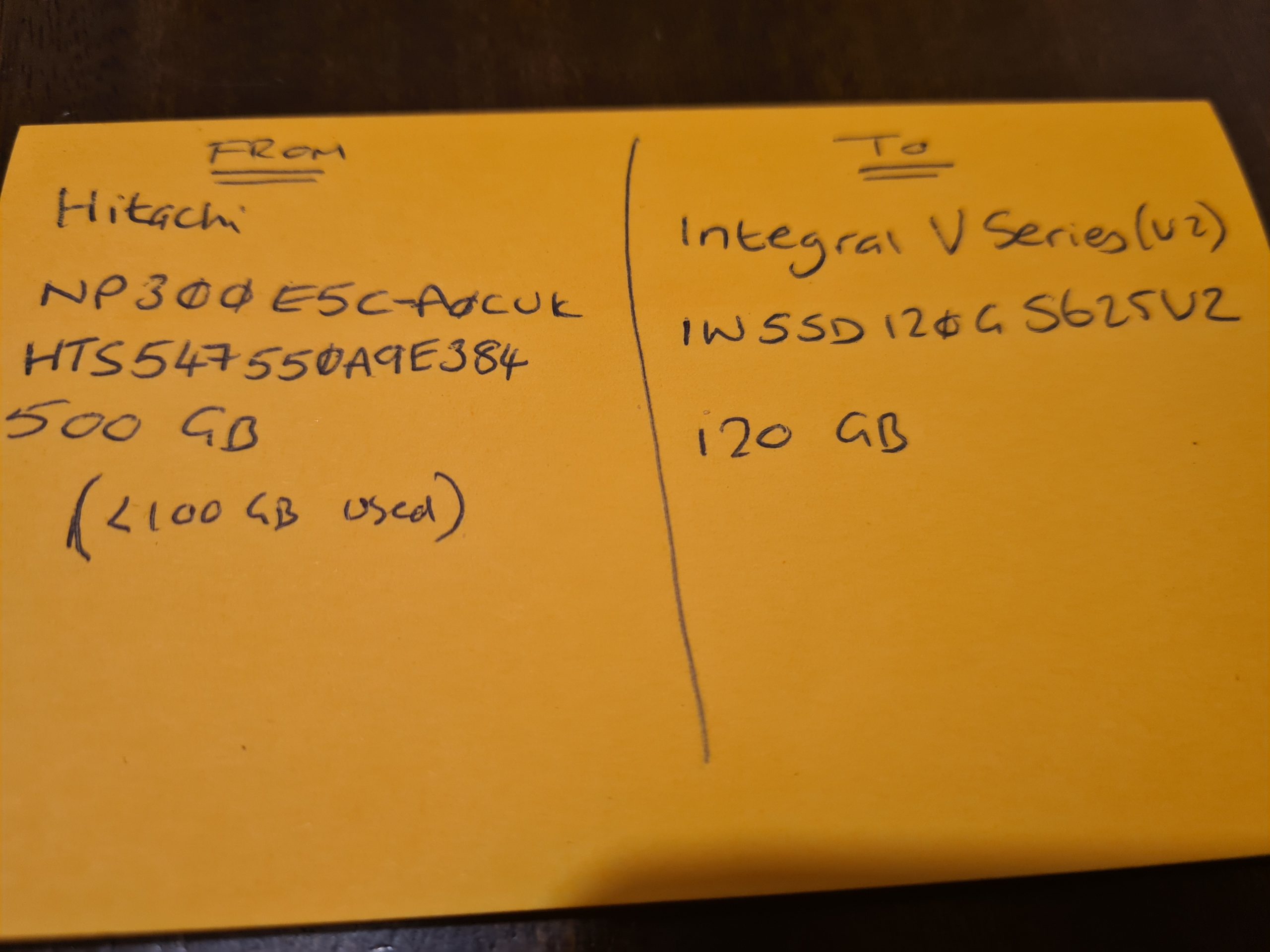
Make a note of the ID of the Disks.
I cannot stress this enough. Make sure you have the IDs of the disks you are working with to transfer data from and to. Make a note of the labels printed on the physical disks so that you can ensure you are transferring data from the right source and to the correct destination.
There is no going back from an incorrect action at this step.
Physical Disks, Partitions and Bootable Disks
Next, before we actually get onto to the migration, it’s important to understand the context. There is a Physical Disk connected to the computer, but then we have Partitions and Boot Partitions to contend with along with both physical and logical volumes. Volumes is just another word for Partition.
This all depends on your specific use case. For example, if the disk you are cloning is from an external USB hard disk, then this probably doesn’t have a bootable operating system setup as it is just there to store basic data. Whereas if you are upgrading your primary disk that runs your operating system, then you will have a Boot Partition which is the part of the disk that runs a piece of software called the Boot Loader which is responsible for booting the operating system you have installed.
For Example;
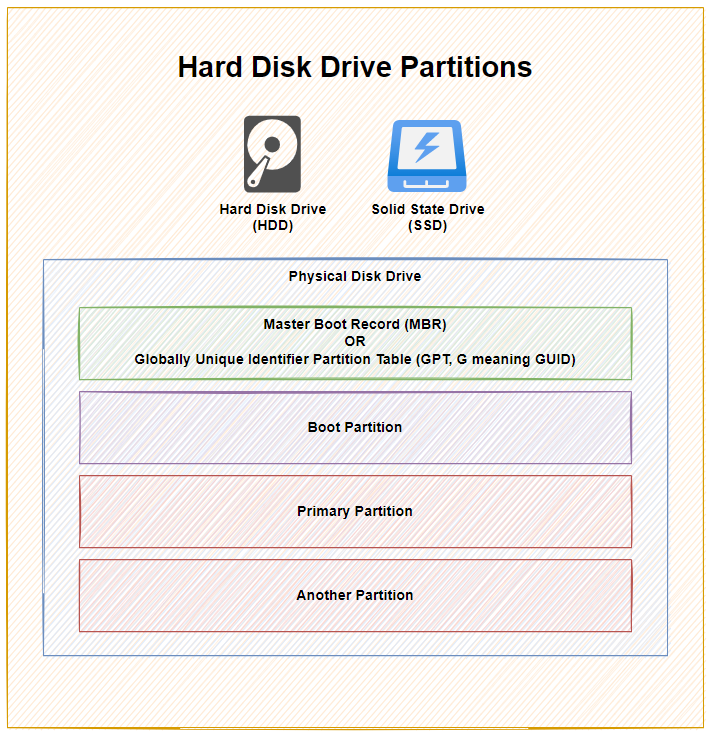
As you can see above, with 1x physical disk drive, whether that is a Hard Disk Drive (HDD) or a Solid State Drive (SSD), they ultimately have the same bits under the hood to make the disk work as it should based on you requirements – either as a Bootable Disk or a Non-Bootable Disk.
To explain a few concepts;
- The Master Boot Record (MBR) was for disks less than 2 TB in size. In reality these days, most disks are larger than 2 TB in size, so as a general rule of thumb, you are probably best always using Globally Unique Identifier Partition Table (GPT) when managing your disks. MBR has a maximum partition capacity of 2 TB, so even if your disk is 10 TB, the maximum size of any one partition is 2 TB, which soon becomes a pain to manage. Compared with GPT which has a maximum partition capacity of 9.4 ZB, so you’re good for a while using this option
- Primary Partition, this is where your operating system is installed and your data saved
- Another Partition, this is just an example where some people use multiple partitions on the disk to manage their data. In reality, for basic disks you are likely only using one primary partition for standard computer use. When you get into the world of Servers and Data Management, then you end up having many logical partitions to segment your data on the disk for the virtual machines using that data, but that’s out of scope of this blog post.
I have seen this a few times in practice when computers have come my way to fix after a ‘professional’ had already apparently fixed something and clearly it wasn’t done correctly. One recent example was with a 3 TB disk drive, yet only 2 TB of it was available for use as it had been configured with only one partition which had a maximum of 2 TB of size. Clearly the person setting this up didn’t really look too closely at anything they were doing, particularly as their primary ‘fix’ was to replace a 3 TB disk drive with a 120 GB disk drive, then the end person using the machine was sat wondering why nothing no-longer worked and the only way they could access their files was from an external USB drive. #FacePalm
Windows Disk Management
So what does all this look like in practice? Well, thankfully Windows 10 comes with a handy utility called Disk Management. To access this, simply right click on the Windows ‘Start Menu’ Icon and click on ‘Disk Management’.
To bring the above conceptual diagram into focus, here is a real example of what this looks like with multiple disks to a computer;
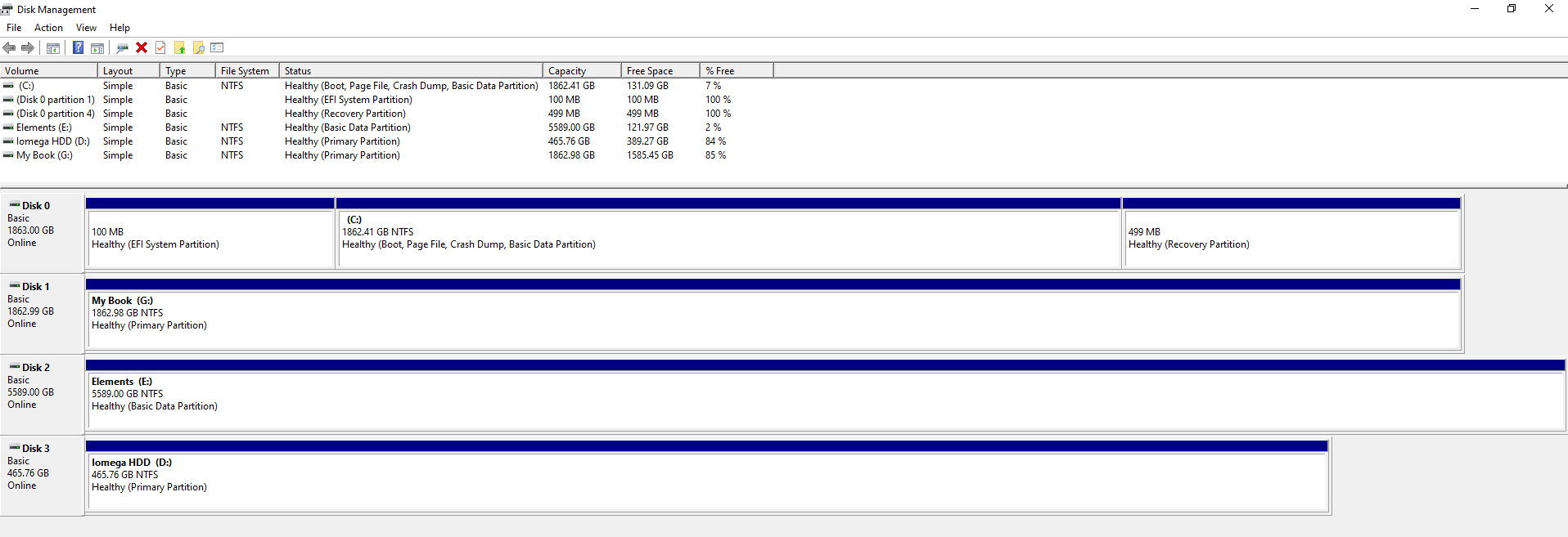
In the above example you can see that there are 4x disks connected to the machine. One is the main disk used for the operating system and the other three are external USB hard drives in this example. What is a tad annoying with this user interface though is that it isn’t clear exactly which disk is which, so you have to be extremely careful. To any user Disk 0, 1, 2, 3 doesn’t really mean anything so at best you have to try and align the disk sizes to what you can see within your ‘This PC’ on your Windows machine.
Thankfully when you Right Click on one of the rows and click on Properties, you can see the name of the disk come up as can be seen below;
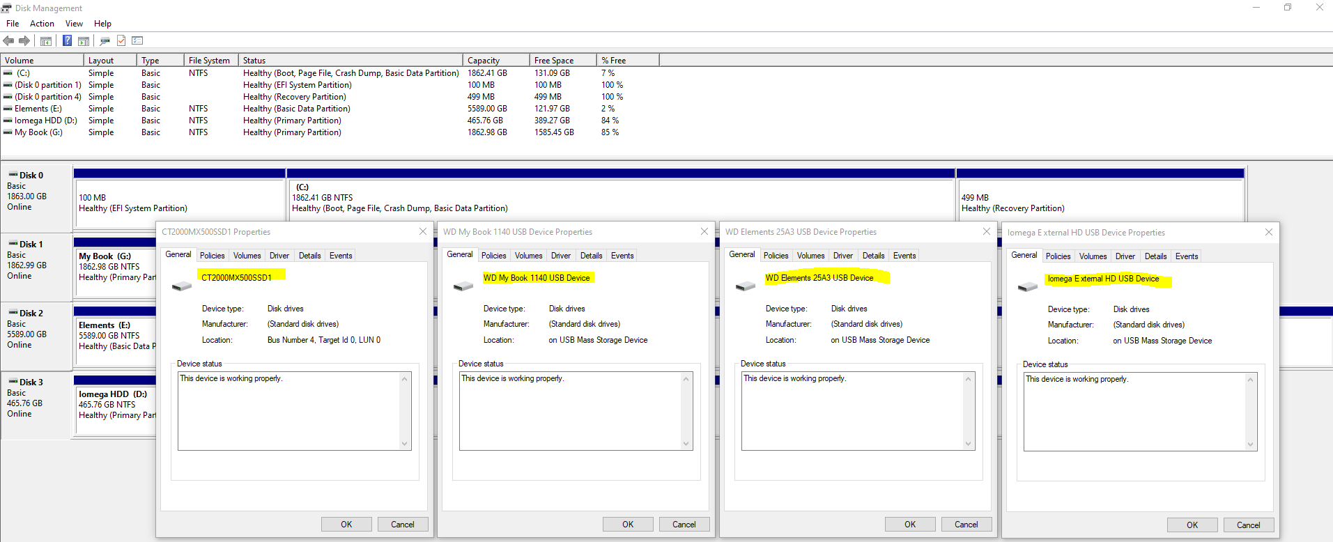
This info will come in extremely handy when you start plugging in some disk drives that you are going to be working with. It’s essential that you are moving data from the correct disk to the correct disk.
Plugging in Your Disks
Ok, so now we’ve covered off the background topics for how to clone a hard disk, it’s time to jump in and give this a go. You must take this a step at a time to ensure you are 1000% confident that you are sure that you are doing the right thing. As I have said many times already, if you get this bit wrong, it’s going to be very disruptive – particularly if like many people you still don’t have 100% of your data backed up in the cloud.
So, here’s what you’re going to need;
- Old Disk
- New Disk (Contact us if you need us to supply and we can price things up if you aren’t sure what you’re looking for)
- USB External SATA Disk Drive Connector / Adapter Cable (buy here)
- USB External SATA, 3.5” IDE, 2.5” IDE Disk Drive Adapter Tool Kit (buy here)
Make a note of the IDs of your disks from the labels on the physical disk drive. You should see these exact names show up in Windows Disk Management Utility Software. It is these IDs that you will need in the next step to make sure you are cloning the data from and to the correct disks.
One item to note is that if you are using a brand new disk for your New Disk, then you will need to Initialise the disk using GPT via Windows Disk Management Utility Software when prompted once it is plugged in. For disks that you are re-using then this initialisation step usually doesn’t appear. For new disks you will also need to right click on the unallocated area of the disk and select New Simple Volume, then give the Volume (aka. Partition) a size and a Drive Letter then you can format the new partition so you can use it going forwards. Then the drive is ready for use.
Clone Hard Disk Software
There is a small handful of software available both commercially and open source for cloning disk drives, with significantly varying usability aspects. For simplicity, we’re going to take a look at one of the easier to use pieces of software called Acronis True Image for Crucial.
Aconis is a commercial product, but many manufacturers have a free Clone Disk feature within Acronis, such as for Crucial Disk Drives the above software works. There are a lot of makes/models of disks on the market, so if in doubt about what software works best with your hardware, then contact the disk drive manufacturer directly via their support channels and they can advise best which software works best with your hardware.
There are also lots of super technical open source options available, but personally I’ve just not had time to play with these since this is fundamentally a basic copy and paste job fundamentally so it should have a user interface for allow anyone to do this kind of thing in my opinion.
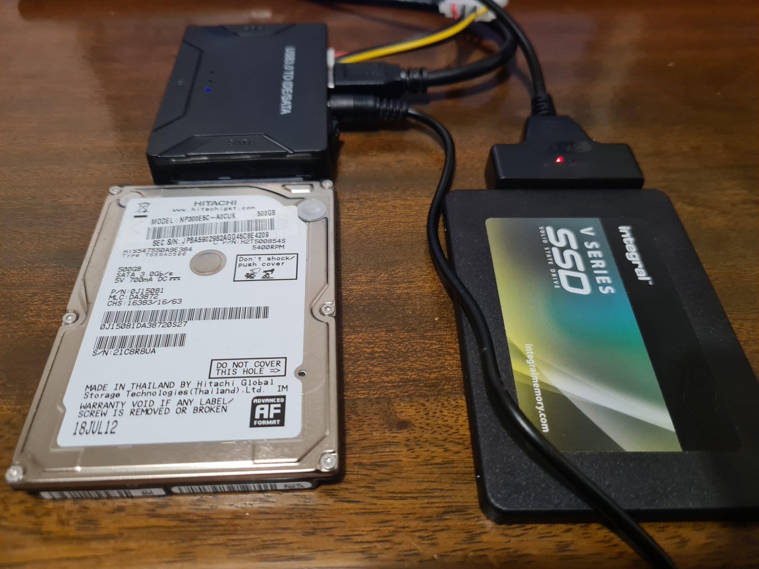
Here are a few images of the setup I was playing with for the purpose of this blog post;
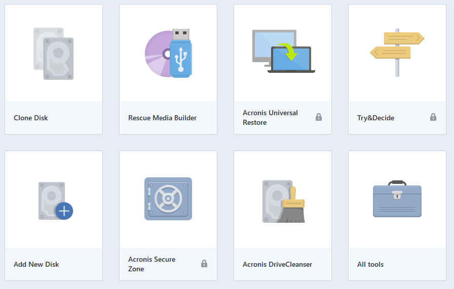
Open Up Clone Disk Tool in Acronis
When you have Acronis open, select the Clone Disk tool. Note, this can take a while to open up, so be patient.
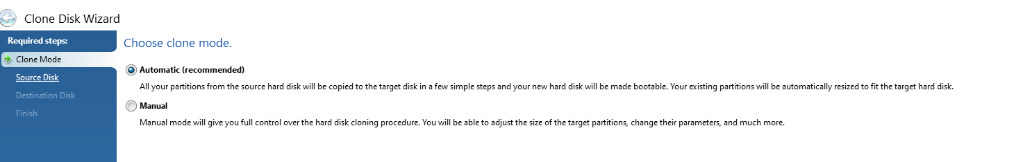
Select Automatic Clone Mode
This is the mode that is most common to use which handles everything in the background for you. The Manual mode gives you much more control but can often be a bit overwhelming if you aren’t too familiar with some of these concepts.
Select Source Disk
This step is particularly important, make sure you select the correct ID that is printed on the hard drive sticker so you are confident you are moving data from the correct disk drive.
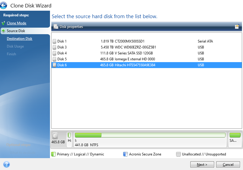
You’ll notice the handy info that Acronis displays at the bottom which shows how the partitions on the drive are currently set up and what is and isn’t being used. This comes in very handy in the next step, particularly as in this case the data is being migrated from a 500 GB HDD to a 120 GB SSD. Your math is correct, that doesn’t fit – but – Acronis is smart enough to only transfer the data that is being used which means that in this scenario the data will fit.
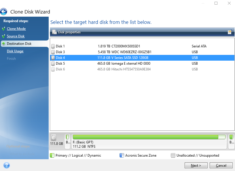
Select Destination Disk
Same as the previous step, make sure you are selecting the correct disk based on the IDs of the disk that is printed on your physical disk.
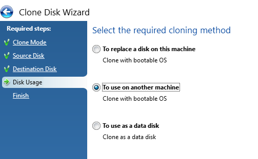
Select the Cloning Method
Next, select the cloning method you are doing. In my case both the old and new disks are connected via USB and are going to be used on another machine, not the machine that Acronis is installed and being run from. Generally speaking, when disk drives start failing, the machine they live in also becomes fairly unresponsive and/or just extremely sluggish. So it’s often easier to whip out the old disk drives and get them plugged into a decent computer that can do the grunt work.
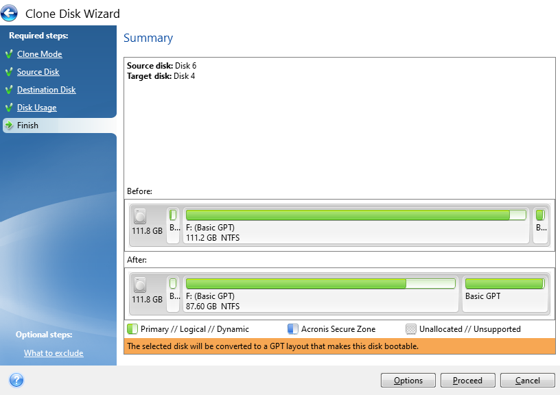
Confirm Settings and Start the Cloning Process
The final step is just confirming what your new disk will look like both at present and after the conversion process. In this example, this is an existing disk that is being flattened and re-purposed which is why the before info shows that the disk is full. If you are using a brand new disk, this will show up mainly empty as there will be nothing on it.
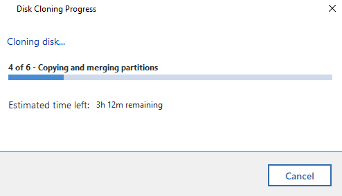
Now it’s just a case of sitting back and waiting. I’ve mentioned already Acronis is a slow piece of software for whatever reason. Just getting to this point probably took around 45 minutes believe it or not. The cloning process takes even longer. So make sure everything has plenty of juice to keep the power on throughout the process or you’ll end up losing a lot of time going through this process again.
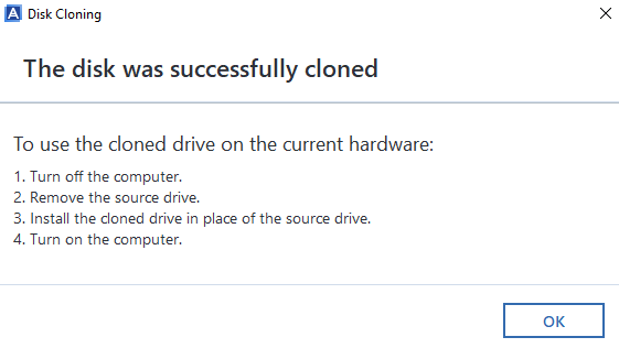
Disk Clone Successful
Woo! Finally, the cloning process has been complete. Now it’s just a case of plugging the new disk drive back into the computer you took the old one out of and everything should be back to normal, working fast again etc. If you do get any problems with this point, then generally the clone will have failed, even though Acronis says that it has worked. i.e. missing a bootable sector or some other form of corruption that is going to be near impossible to get to the bottom of.
Backups, Cloud, Redundancy Etc.
Ok, so we’ve run through the process of cloning hard disks either from HDD to HDD, HDD to SSD or SSD to SSD. Whatever your situation has been. What we haven’t covered off on this blog post yet is around backups, cloud and data redundancy etc. So let’s keep this topic really simple… your hard drives will fail at some point, so plan for it.
Use cloud service providers for storing your data, they have endless backups in place that are handled for you automatically without ever thinking about it. If you only have your data on your main hard disk in your computer, there is a chance that when your disk fails, you will permanently lose your data. Do not go backing up important data to external hard drives, this is manual, error prone and is still likely to result in some data loss for your data when one or more of your hard drives fail.
This is a topic that I could go into for a long time, but will avoid doing so within this blog post. Instead, let’s just keep things simple and ensure your data is backed up to the cloud. And make sure you can easily recover from a failed hard disk and be back up and running within hours, not weeks.
Notes on Failing Disks
Important to note that if you are working with a failing disk, then you can pretty much throw all of the above out of the window. Give it a go, but it’ll probably fail. You are probably best off getting a new disk drive and installing Windows 10 from scratch then you can copy the files over that you need (and backing them up to the cloud!). It’s a bit painful doing this but often it’s the only route when the disk drive has gone past the point of no return and is intermittently failing and doing random things. I’ve seen random things such as monitors flashing on/off with the Windows desktop going blank then back again on a repeat through to disk recovery software failing when it tries to read one single bit of data on the disk, usually about 95% into the process. It’s always best not to get to this point. Some other nuances I’ve seen is that BIOS wasn’t detecting the disk after an apparent successful clone, yet I could see the drive in Windows Device Manager when plugged into another machine, but it wasn’t showing up in Windows Disk Management. All very odd.
When thing get to this point, it’s time to just give up on the old disk, get Windows installed on a brand new one and salvage what you can. Learn your lesson and don’t make the same mistake twice. There are advanced recovery (and costly) options available to do deep dive recovery of data, which again on failing disks can even still be a bit hit and miss so you could be throwing good money after bad trying to recover this data, but it all depends on how important that data is to you.
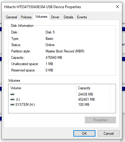
Check What Your Old Disk is Using – GPT or MBR
Something we didn’t go into in too much detail so far but is important to mention. GPT VS MBR – Make sure you check what the old disk is configured as. Or you’ll be repeating the processes again, or be forced to use a commercial bit of software to change GPT to MBR or the other way round. To do this, within Windows Disk Management, simply Right Click on the old drive and select Properties, then click on the Volumes tab where this info will be displayed. In this case we can see that the old drive is using MBR, so it’s best to configure the new disk drive also to use MBR because the computer this came from could (and likely will) have certain limitations at the BIOS layer about if MBR or GPT is supported (aka. UEIF Mode either Enabled or Disabled).
Note, Acronis is a pretty dumb and opinionated piece of software. It assumes that the Destination Disk Partition Mode (MBR VS GPT) is determined purely based on the computer that Acronis is running on. This is dumb, and quite frankly a fundamental flaw in the software in my opinion. In the vast majority of use cases in my experience, the Source Disk and Destination Disk are going to be plugged into an independent computer that is merely there to perform the copy and paste job.
MBR VS GPT is a Legacy VS Modern topic that is beyond the scope of this blog post. But what is important to note beyond the disk drive is that this comes down to the Motherboard’s BIOS Settings in relation to UEIF which is either Enabled or Disabled. Even still, there can be many compatibility issues in this space.
Sometimes, it’s just more effort than it is worth trying to upgrade a computer though. If it’s old, the Old HDD is old, then all the other components are old and slow. Sometimes it’s just more economic to throw away (recycle) the old and get a brand new computer and/or start with a fresh installation of Windows and go from there.
There are many bits of software that can help with cloning disks include: Clonezilla, Macrium Reflect Free, DriveImage XML, SuperDuper and many more. Many come with free basics and trial periods, but generally if you want to do something in full with an easy user experience, then you’re going to be using the commercial offerings.
After personally getting rather frustrated with Acronis, I decided to have a little rant on the Acronis Support Forums. Summary being “Unfortunately this is very unlikely to change for all users of Acronis True Image! This is because Acronis no longer support or develop this product.” And “The MVP community have been asking for this for some years but without any success.”. Not a very positive message, but at least an honest one from a senior member of the community given the lack of engagement from Acronis directly.
Summary
Hopefully this has been a helpful and detailed blog post for how to clone a hard disk drive (HDD) or solid state drive (SSD) and how you can handle this process for either failing disks or just upgrading disks to newer, faster and larger models.
Please take care when performing these actions and if you aren’t sure what you are doing, then leave this to the professionals. There are a lot of nuances with these types of actions which can be extremely destructive if you get this wrong. Be careful.
by Michael Cropper | Jul 25, 2022 | Developer, IT, Networking |
First of all, networking is a challenge in itself to understand what you want to achieve and how to configure things to make them work. It’s made even harder when basic things that should just work, for some reason don’t due to one reason or another. This blog post is off the back of one of those niggles that was driving me crazy trying to understand why something wasn’t working when it should have been and it turned out the answer was pretty simple when I finally got to the bottom of it.
Before we jump into the details, let’s make sure we’re all on the same page.
What is Ping?
Ping is a command line utility that is designed to test the reachability of a hostname or IP address. In simple terms, it’s a way of your computer saying “hello” to another computer and waiting to see if the other computer responds and says “hello” back – or just ignores you.
To use the ping command, it’s as simple as running either of the following commands via your command line either on Windows or Linux and is often packaged on Linux systems through the iputils package from Yum etc.
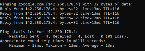
ping google.com
Which will respond as follows if a successful connection is made
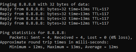
ping 8.8.8.8
8.8.8.8 is the primary IP address of Google’s public DNS system if you’re not aware, with 8.8.4.4 being the secondary IP address. When ping’ed this will respond as follows if a successful connection is made
ping a-website-that-doesnt-exist.com
Here’s what happens when you don’t get a successful response such as when in this example, there is no DNS A Record against that hostname so the hostname cannot be successfully translated into an IP address.

ping 192.168.3.201
Now let’s say that you have a computer on your network that you know exists and you know it is turned on. When you try to ping that IP address, you should receive a successful message as shows above. But in some situations you may get errors such as “request timed out”
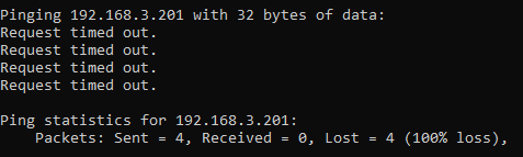
This is where things get a little fun trying to debug these things, which we’ll cover off in this blog post.
Ping Summary
The above various examples are what both success and failure messages look like when using the ping command line utility. So you know what to look out for when debugging why ping isn’t working.
What is ICMP aka. Internet Control Message Protocol?
The ping command line utility utilises ICMP, the Internet Control Message Protocol. I’m not going to go into too much detail with this one as we could go down a fairly deep rabbit hole around the Internet Protocol Suite, IEFT and RFCs (Request for Comments) such as RFC1918 which is the protocol that outlines what IP address ranges can be used publicly and which ones are reserved for private usage. We did a blog post covering what RFC1918 is a few years back to help people understand this in a simple way.
Anyhow, to keep things simple ICMP is essentially a supporting protocol as part of the Internet Protocol Suite that is designed to capture success/failure type messages when one host is trying to communicate with another host. Just like in the examples we gave above using the ping command line utility. The reality is that there are a whole host of protocols that the average technical user has never even heard of unless you’re a network specialist such as: TCP, UDP, ICMP, ESP, AH, GRE, EoIP, IPV6, IGMP, PIM, OSPF, SCTP, CARP, PFSYNC. Most people have heard of TCP, some know of UDP, but the rest most people have never heard of and will never need to know anything about.
In reality, ICMP is used by things that are primarily under-the-hood technologies that most people haven’t ever heard of and/or don’t really care about. The exception being command line tools like ping and tracert/traceroute commands which are designed for humans to be using to help with debugging.
Why all of this is important is because ‘a’ firewall along the journey from source to destination could be blocking ICMP traffic which would cause your ping command to fail, when you would expect it to be working.
Understanding the Route of the Network Packets
Now comes the fun part. While things often seem relatively straight forward that Computer 1 wants to talk to Computer 2, the reality is that things under the hood are 100x more complex than this and have so many nuances and company specific configurations that it’s never as straight forward as it should be to debug basic things like this.
Hence why it’s essential that you understand how things are configured under the hood. Unfortunately in my experience in most enterprise organisations, no-one really has a clue how all this actually works and why it works, it just kind of does for the average non-technical user so organisations kind of accept that because it just works, let’s not to prodding it. Ultimately this is an extremely bad thought process to have and when leadership doesn’t question these things, this ultimately causes endless headaches for IT staff doing their daily work because things that should just work often don’t and often require weeks, even months in many cases of time spent on meetings/emails/conversations to ultimately understand what should have really been a 5 minute fix to a problem.
Even worse in some organisations whereby it soon becomes a case of networking/firewall/configuration whack-a-mole whereby people start fiddling with the settings without understanding things fully which solves one problem but creates 10x more which get reported days/weeks later when other things start to break. This stuff is hard, it requires extremely knowledgeable individuals to make informed decisions to configure things well.
Anyhow, back to the main point. You need to understand how things work. How do packets get from Computer 1 to Computer 2 when you are ping’ing the IP address or hostname?
Let’s look at an extremely basic setup and the hops along the way;
- Source Computer sends ping command to Destination Computer
- Source Computer outbound firewall – Does it allow outbound ICMP traffic?
- Network Router/Firewall/Gateway – Does it allow ICMP traffic through from the Source Computer to the Destination Computer?
- Destination Computer inbound firewall – Does it allow inbound ICMP traffic?
And this is where things get even more challenging, since there can be configurations on Windows such as Public and Private networks that you connect to. Let’s be honest, the average user configuring this on their own machines hasn’t got a clue what to select and just randomly click one of the two options. In reality though, depending on what a user clicks on will depend on how Windows behaves and ultimately in this example if Windows response to ping requests or completely ignores them.
Windows Firewall Public and Private Networks
To keep this section focused on the topic at hand, debugging ping requests not working as they should, we’re going to simply take a look at the two common Windows network settings – Public Network and Private Network.
Your device will either have one or both of these options;
- WiFi Network Interface Card (aka. No cable plugged into device)
- Ethernet Network Interface Card (aka. Cable plugged into device)
And each of these within your Windows Network and Sharing Centre will either be configured as a Public Network or a Private Network. By default on Windows, if a NIC (Network Interface Card) is configured to be used as a Public Network, then inbound ping requests will be ignored, whereas if the NIC is configured to be used as a Private Network, then inbound ping requests will be responded to.
Rather annoyingly on Windows, once this initial configuration is done (in most cases incorrectly…) then changing a NIC from Public to Private or vice-versa is not as simple as clicking a button – you have to use Windows Powershell. There should be no reason to do this in 2022, but hey, send your complaints (aka. “feature requests”) into Microsoft to solve this one.
For anyone needing to do this, here’s how to change a Windows network from private to public or how to change a Windows network from public to private;
- Open Windows PowerShell as an Administrator
- Run command:
- Get-NetConnectionProfile
- Which will show you the network type, i.e. either public or private
- Run command:
- Set-NetConnectionProfile –Name “{NAME OF YOUR NETWORK}” –NetworkCategory Private
- Which will set the name of the network to either Private or Public depending on what you type in the above command
- Then when you open your Network and Sharing Centre, you should see that the network has changed from Public/Private to the opposite of what it was previously.
Norton 360 Smart Firewall Blocking ICMP Ping Requests
Another one of those annoying “features” is when Windows based firewall software overrides the default Windows firewall, adding another layer of debugging to a problem. In this case, software such as Norton 360 Smart Firewall essentially takes control of the firewall management rather than Windows out of the box. This is where things can get messy.
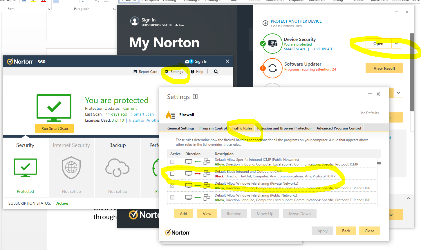
End user firewall software, regardless of brand, tend to dumb things down to such as level that they often hide the complexity of the details which are often hard to find in the system. Norton 360 is a prime example of this. By default it blocks inbound ICMP traffic, meaning that if you are trying to ping Computer 2 (with Norton 360 on) from Computer 1, then by default pings will fail. You need to allow ICMP traffic within the Norton 360 Smart Firewall settings to ensure that this traffic can pass through to Windows to respond successfully.
You can see here how deep the settings for this are buried within Norton 360 Smart Firewall, it’s almost impossible to find this without knowing exactly what you are looking for, which 99.9% of users simply haven’t got a clue about.
The irony being that there is nothing “smart” about this setup, it’s simply fully of dumb assumptions being made in the guise of security. These kinds of configurations are an absolute pain to deal with as they are never well documented out of the box about what is the default configuration, which ultimately results in people digging and digging and digging to get to the root cause of why something that should be working isn’t working. Hey, the joys of IT I guess. It does annoy me though around all these assumptions that are made by software vendors to try and “help”. The best help they could give is write better documentation and/or build their software in a way that caters for different types of users from basic to power users and documentation that helps even the most computer illiterate individual understand what they need to configure. Most companies don’t seem to get this basic concept though, unfortunately.
Summary
I hope that this blog post has given you some guidelines and thoughts about how to debug and troubleshoot issues when commands like ping and tracert/traceroute aren’t quite working as expected. What you’ve hopefully picked up is that these things aren’t straight forward to debug.
The best advice I can possible give is to be methodical at every step along the way. Aim to understand every hop along the journey, and confirm for every hop that traffic is successfully leaving the hop and successfully arriving at the next hop along the way.
It’s not straight forward and requires an exceptional understanding of the underlying infrastructure, which often isn’t easily accessible particularly within enterprise organisations. It’s not easy debugging these kinds of things with every hand/arm/limb/sense tied behind your back.
by Michael Cropper | Aug 31, 2021 | IT |
BIOS boot modes, something that is so long standing in the IT industry which never changes, it had a single option which was the BIOS boot mode. The usual blue screen that only works with a keyboard and not a mouse, the blue screen that you have to access from the black screen on boot usually by repetitively tapping on either the F10, F2, F12, F1 or DEL key, depending on your motherboards manufacturer. Simple right? No. It’s an absolute nightmare.
But hey, we’ve got a newer and upgraded version of BIOS, and it’s called UEFI. UEFI was actually launched officially as a standard back in 2006 believe it or not. The time from when a standard is launched vs how quickly this moves throughout the IT hardware manufacturers is often measured in years, not months or days. So actually this is a fairly ‘new’ thing and many consumer hardware manufacturers only started to phase this technology into their systems around 2017.
The whole point of UEFI is the concept of Firmware-as-a-Service which is focused around extensibility rather than fixed approaches. What this means is that UEFI is designed to allow the utilisation of large disk partitions of over 2TB in size along with a modular design which enables both backwards and forwards compatibility.
Fundamentally the difference between BIOS and UEFI comes down to the link between the hardware and boot loader layer on your drives and bootable devices connected to your system. Think of this kind of like the ‘Construct Program’ in The Matrix – you can load whatever you want, given the constraints of the system.
In the real world what this means is that traditional BIOS systems are based on a more simplistic limited memory/capacity systems of computer chips. Whereas UEFI is capable of operating on systems that have more advanced hardware chips within their systems. Hardware and software are intricately linked. UEFI stands for Unified Extensible Firmware Interface.
One of the huge benefits from a user perspective is that within UEFI you can actually use your mouse to control the system rather than everything being keyboard driven in the Legacy BIOS system. Beyond that, you are probably never going to need to worry about these differences – that is until something doesn’t work as you expect in relation to a piece of hardware not booting correctly. This is where things are a bit messy and it’s going to take likely another decade until things fully iron their self out.
As a general rule of thumb, for modern hardware, just use UEFI to Boot. For older hardware or older operating systems, you may have to use Legacy Boot to get the machine to boot up successfully.
Rather than re-invent the wheel, here is a handy source of the core differences between Legacy Boot mode and UEFI Boot mode;
What is a difference between UEFI and Legacy Boot settings;
- Legacy is traditional and very easy method which had worked absolutely fine so far.
- UEFI is critical, 1709 was the first perfect OS which worked best with the OS.
- Legacy has best in performance had minimum boot issues and easiest to install.
- UEFI is now stable, but yet most of the IT tech do not now how to use this feature and correctly install the OS.
- Legacy was safe and secure and very user friendly, it is just that you can select the boot device which you want to boot from and it search for Master Boot Record MBR and used to pick it up.
- UEFI is market as more secure but there is no more security just that it supports TPM which enables Bitlocker and has extra headache to mention the EFI boot manager, which is no secure if you have access to BIOS and did it few times earlier just like Legacy.
- Legacy has maximum partitioning size of 2 Terabyte.
- UEFI has partitioning size of 9 Zetabyte which is huge.
- Legacy can have 4 Primary Partition.
- UEFI can have 128 Primary Partitions.
- Legacy is good for loading 2 OS on same system.
- UEFI is Great for loading more than 2 OS on the single system.
- There are more differences and UEFI is way beyond the Legacy BIOS technology but it has not yet revealed its troe power.
- Legacy uses Master Boot Record.
- UEFI uses GUID Partition Table.
- Legacy is traditional Firmware which interacts with Motherboard and OS.
- UEFI is also just a Firmware with advanced options.
- Microsoft New OS will no more support Legacy they have transformed now.
- Microsoft stop support for Legacy OS after launch of 1709 WIndows update.
- The last best Hard Drive supported by Legacy BIOS is SATA SSD.
- The Last Best Hard Driver supported by UEFI is M.2 PCIE SSD Hard drive which does not work on Legacy BIOS.
- Legacy Supports the SSCM in traditional way like you can enable PXE boot and select option to Boot From Network through LAN.
UEFI also supports and enable options to boot from traditional network which is IPV4 as well as IPV6. UEFI firmware is keeping all possibility of future options. To enable it you need to enable UEFI Network Stack which will give option for IPV4 and IPV6.
by Michael Cropper | Mar 18, 2021 | Client Friendly, IT, Networking |
Ok, so you’ve got yourself a nice new Ubiquiti UniFi AP-AC-Lite Wireless Access Point to modernise your network – Awesome. If you are still in the research stage, then take a look through a recent blog post about Unboxing and Testing the Ubiquiti UniFi Access Point AP-AC-Lite so at least you can see what you get in the box and some of the awesome reporting statistics that you can see once you have the device up and running. We’re not going to be covering the topics that are covered in that blog post, we’re going to assume you’ve got it out of the box and have plugged it in then we can look at how to actually get it set up on your network – since plugging the device in itself isn’t enough with UniFi equipment.
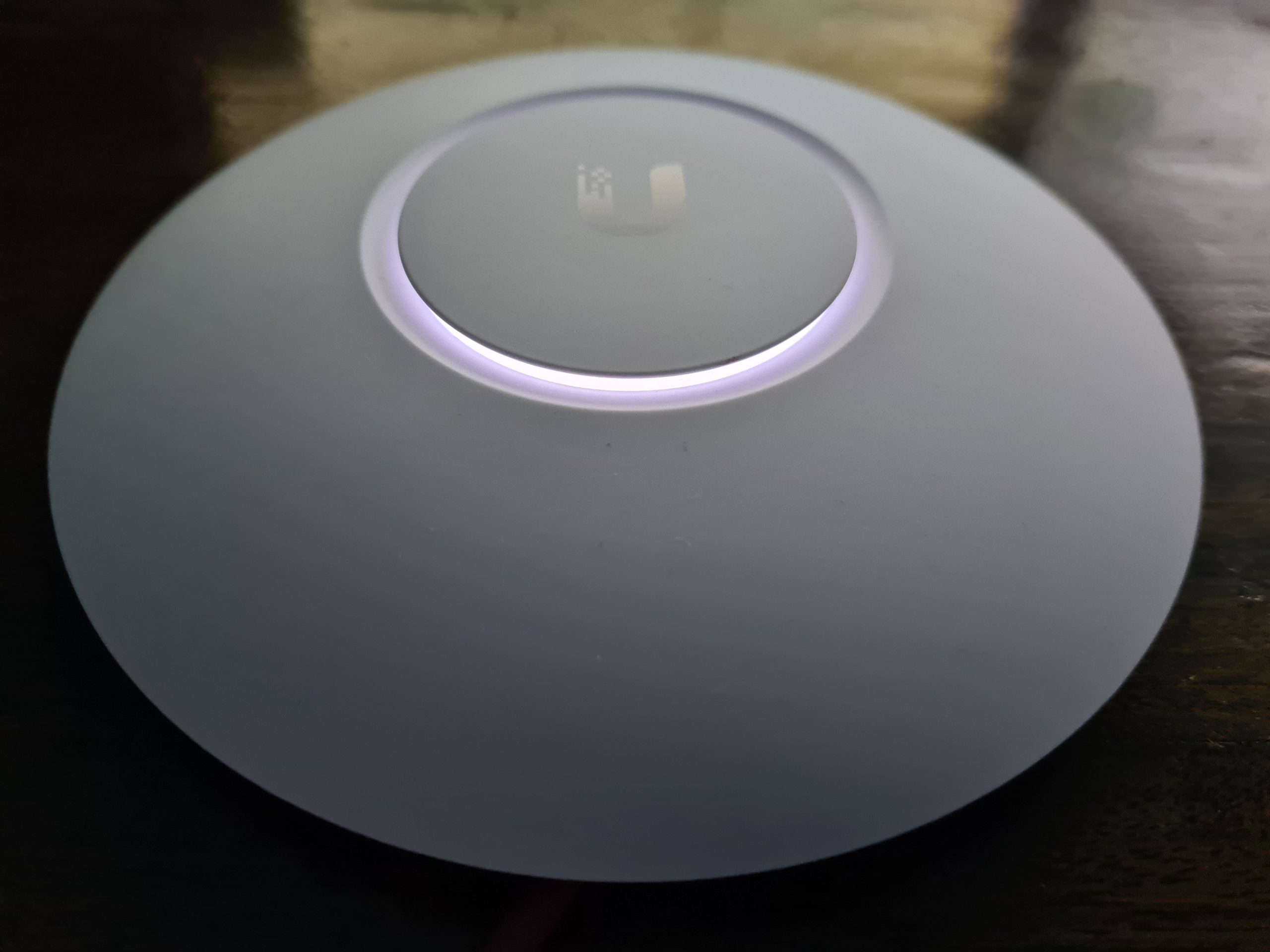
First Plugin of UniFi AP-AC-Lite Wireless Access Point
Ok, so now you’ve plugged your device into your network, it’s time to bring the device onto your network. What I mean by that is that just because you’ve plugged the device in, unlike many other IT network hardware equipment where you plug it in and it’s automatically available for use without configuration (albeit, without configuration certain manufacturers and devices would cease to work anyhow…), with the UniFi equipment you need to officially welcome it onto your network as a trusted device. This process is called the Adoption process.
Once you’ve got the device plugged in, you’ll notice that the physical device has a solid white light on, then turns to a flashing white light for a minute or so, then turns back to a solid white light. What this means is that your device is not yet adopted by your network.
And here’s what that looks like in your UniFi Controller Software. If you aren’t sure what that is, we’ve done a few other blog posts that cover this off in a bit more detail including How to Setup a Ubiquiti UniFi Managed Switch On Your Network so take a read over that if you haven’t yet got your UniFi Controller Software set up and running.
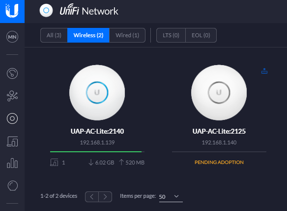
In the above image you can see there are two wireless access points on the network, one that has already been adopted and one that is yet to be adopted so you can see the difference for how the devices display.
Adopt the UniFi AP-AC-Lite Wireless Access Point Device
To welcome your new device onto your network officially simply click onto the device that is pending adoption which will open a pop out window as can be seen below;
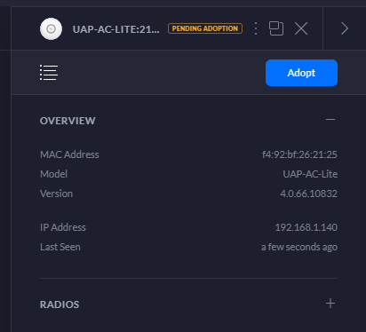
Simply click on the Adopt button to get started. Once you’ve done this, you’ll notice the status of the device turn to a blue light and within the UniFi Controller Software the device will switch to Pending Adoption, then Provisioning. Once it’s done you’ll notice the device is ready to go;

Then you’ll notice that your device is ready to go within the UniFi Controller Software too. The device doesn’t have a green light beneath it as there are no connected wireless clients connected to the device yet.
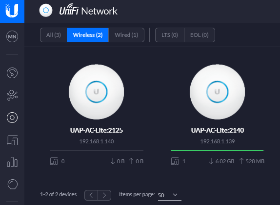
One point to note is that if you’ve just received your UniFi Wireless Access Point, then it’s highly likely that there are some updates waiting for you to install on the firmware itself. You’ll notice a little icon in the top right of the device in the above image (not shown, as all devices are up to date) so just click on that and get your devices up to date. There is always going to be the natural lag between when the firmware was originally installed at the manufacturing plant to when it arrives on your doorstep. So thankfully with smart software technology and smart devices you can easily bring your devices up to date with ease. Traditional legacy network hardware often isn’t as smart with this, although many do try to have some form of notification that there are firmware updates ready for installation, once you can find the hidden notification in the system.
Configure a Wireless Network
Now that you’ve got your devices connected, you need to create yourself a wireless network. Out of the box you don’t get a wireless networks configured, you need to configure this yourself. This mainly consists of two parts;
- Creating an SSID, aka. a Service Set IDentifier, or more commonly known as the broadcast name of your wireless network like what you see when you try to connect to local wireless networks, it’s the name that identifies itself
- Giving your wireless network a password so that your users can connect securely
To do this, simply navigate to your Settings page (bottom left of the UniFi Controller Softwre, the Cog icon). And you’ll be able to create a wireless network within there. For simplicity in this blog post we’re going to just look at a LAN, so no VLANs and complex Profiles etc. Just so you can get up and running quickly. Top tip – Switch to the Classic Settings user interface as at the time of writing, this still supports more features and functionality. You’re probably fine with basic networks using the more modern interface, but you’ll soon find that basic networking infrastructure settings are invisible in the modern interface at the moment, they will be coming in due course though.
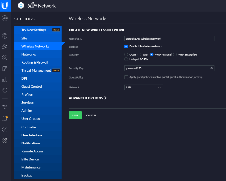
And before anyone points out the obvious…. Yes, give your wireless network (SSID) a decent name and don’t choose ‘password123’ as the security key. Also you probably don’t want to select the option to be an Open network from a Security perspective. This is rarely a good idea, and even when you’re using secure VLANs, you should really consider this from a business perspective before providing open, free and inconspicuous WiFi connectivity as there are legal considerations you need to make. But anyhow that’s for another conversation at another time, so for now, that’s how you set up a basic wireless network for your UniFi AP-AC-Lite Wireless Access Point device (and any other similar models…). Once you’re done with this, you’ll then be able to connect to your wireless network from any devices within range. Simple.
Summary
Awesome, you’re good to go! We’re going to keep this blog post simple and not cover anything related to VLANs or managed switches and unmanaged switches. We’ve covered some of these topics before and we’ll be covering some of the other topics in the near future. For now, you’re all set up with your Ubiquiti UniFi AP-AC-Lite Wireless Access Point so you’re good to start using it.
Hopefully this blog post has been useful to get you up and running with a very basic network configuration using the Ubiquiti UniFi AP-AC-Lite Wireless Access Point on your network. There are many different models from the UniFi range that this same logic applies to for your UniFi Wireless Access Point devices, so this isn’t really specific to this model.
by Michael Cropper | Mar 16, 2021 | Client Friendly, IT, Networking |
I wanted to do a quick unboxing blog post on the Ubiquiti UniFi Access Point, AP-AC-Lite, so that you know what you’re getting when you make the purchase. This will be a fairly quick blog post.
UniFi Access Point AP-AC-Lite Unboxing
First of all, one thing that really stands out with the quality of the box, how well packaged the device is inside the box and just the general feel of all the hardware your are touching, it just feels good quality. You know what I mean by this if you’ve handled a lot of different computer and network hardware, you can really tell how well something is made just by having a good touch and feel of it.
The UniFi AP-AC-Lite model from UniFi is their basic entry level access point which is designed for smaller number of clients accessing the access point. The reality is that there is no hard and fast rule for how many clients any access point can handle, you have to use your judgement on this based on the information you have at hand. And even then, you’ll probably get it wrong at times even with lots of experience – and that’s just the reality of working with IT hardware, sometimes you need to adjust depending on the reality of your use case in the real world.
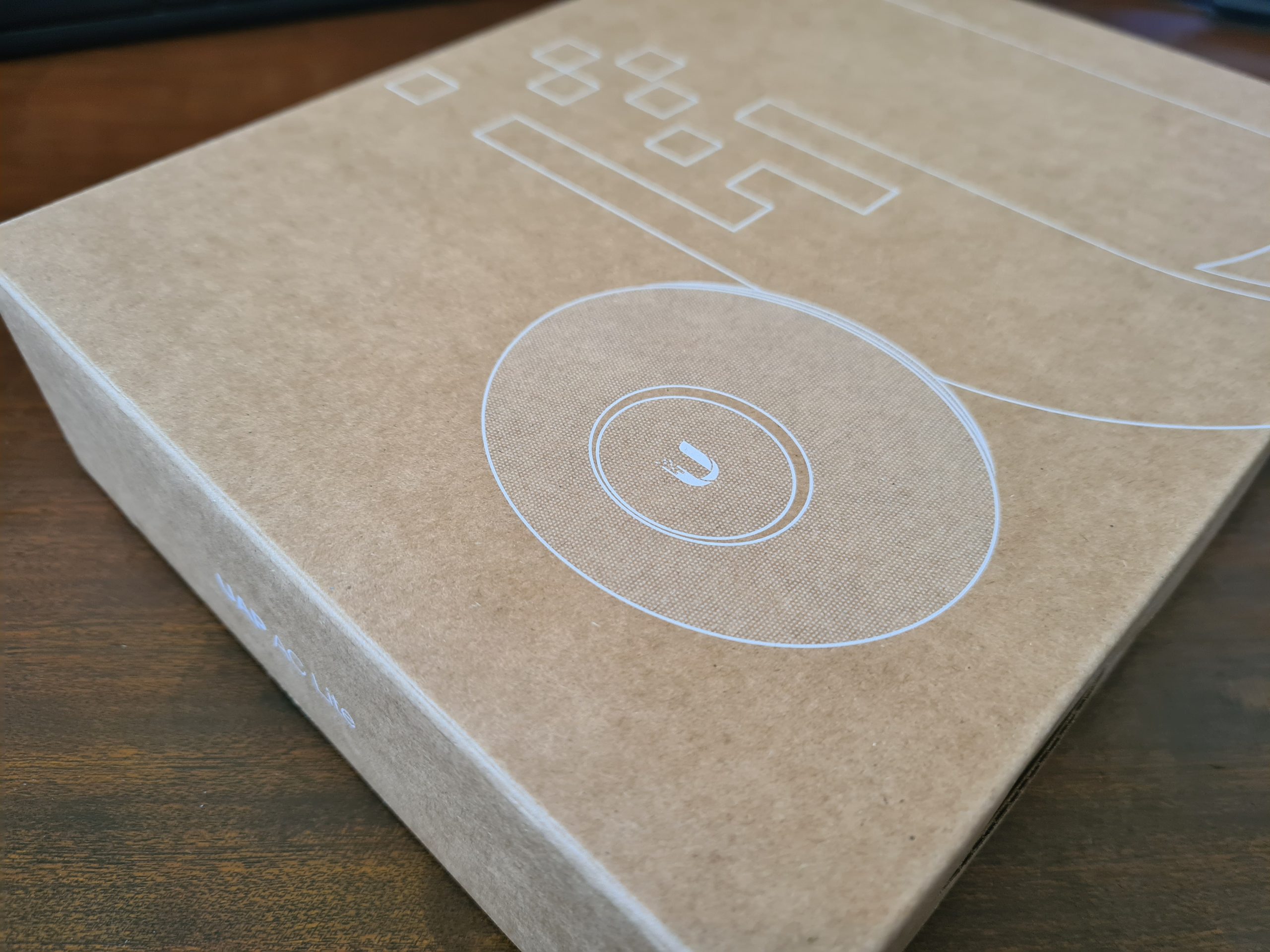
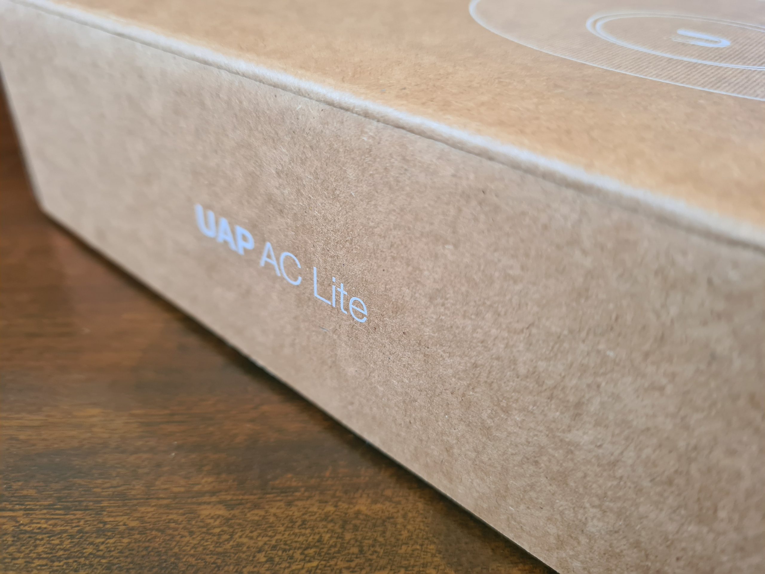
The Box
One thing that is very noticeable when you get the UniFi Access Point AP-AC-Lite is that the box just feels nice. It feels extremely good quality from both the weight and the texture. It’s clear that they have thought a lot about these products right from the outset – even before opening the box.
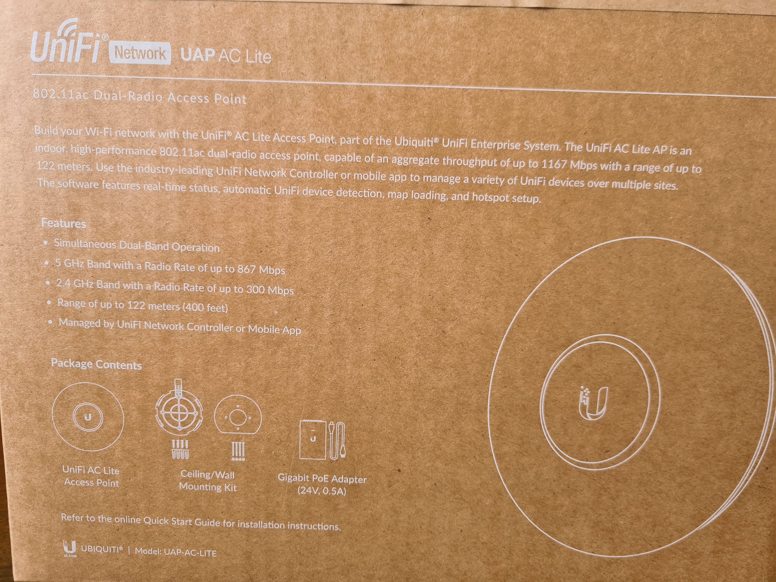
What you’ll notice in the image below is some of the core components that are waiting for you inside the box itself. You’ll find the UniFi UAP AC Life device itself along with a ceiling/wall mounting kit (including screws) plus a very handy Gigabit Power over Ethernet (PoE) adapter which can come in very useful if you haven’t got PoE capable switches (or capacity!) for where you are planning on connecting your UniFi access point to. Quite handy to know is that this UAP AC Lite device is capable of reaching a range of up to 122 meters, aka. 400ft. For larger distances, the Ubiquiti UniFi range of hardware has better devices capable of broadcasting over longer ranges. Always be sure to know as much as you can about the variety of UniFi hardware available prior to making a purchase. Speak to your knowledgeable expert on the topic.
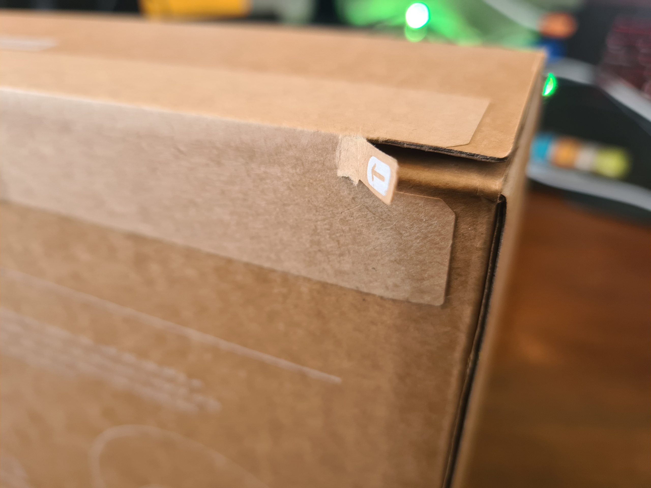
What is a nice little touch on how the UniFi AP-AC-Lite device is boxed up is the Amazon/USA style rip-to-open outer packaging. It is a nice feel that you are opening a product that is being delivered. This being said, it’s a huge hope that what is being delivered is suitable for your specific needs. Once opened, the returns policy is going to be very dependent on the local distributor from whom you purchased the device from. Most IT hardware suppliers are happy for you to return hardware as long as it is in a re-saleable condition, and unfortunately this is the only one slight drawback we have about this packaging, that is isn’t re-saleable due to the outer packaging design. But hey, the UniFi AP-AC-Lite Wireless Access Point works so well, that it’s unlikely that you’ll be returning this anyhow.
Inside the Box for the UniFi AP-AC-Lite Device
Ok, so here’s what we’re presented with once we’ve unpackaged the UniFi AP-AC-Lite wireless access point device. Just to re-iterate, the packaging between the boxed version above and the unboxed version below is extremely well packaged. Super compact and extremely well packaged to manage the terrains of product transit through the worst of delivery companies.
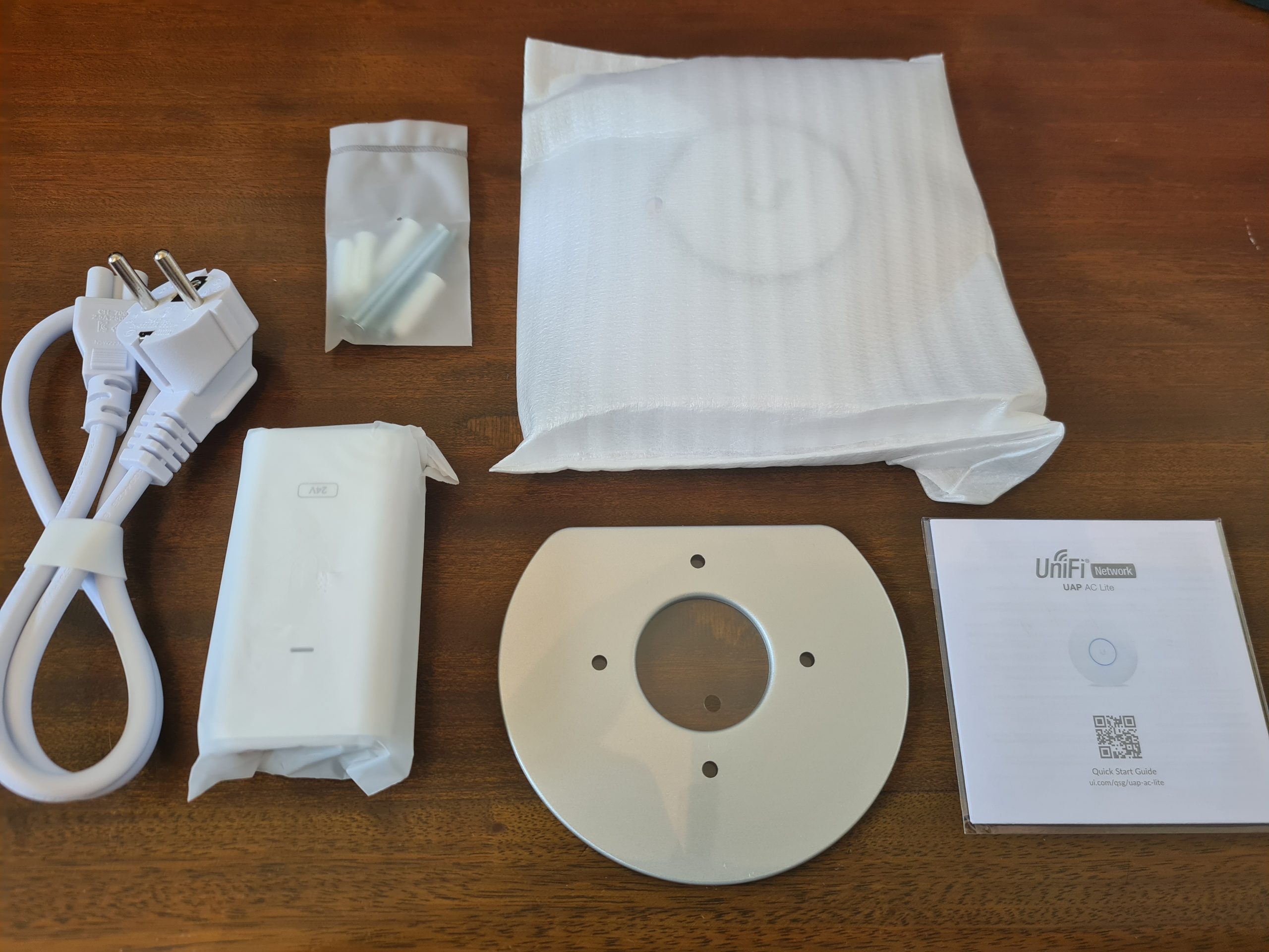
What you’ll notice above is that we’ve got several core items within the product box;
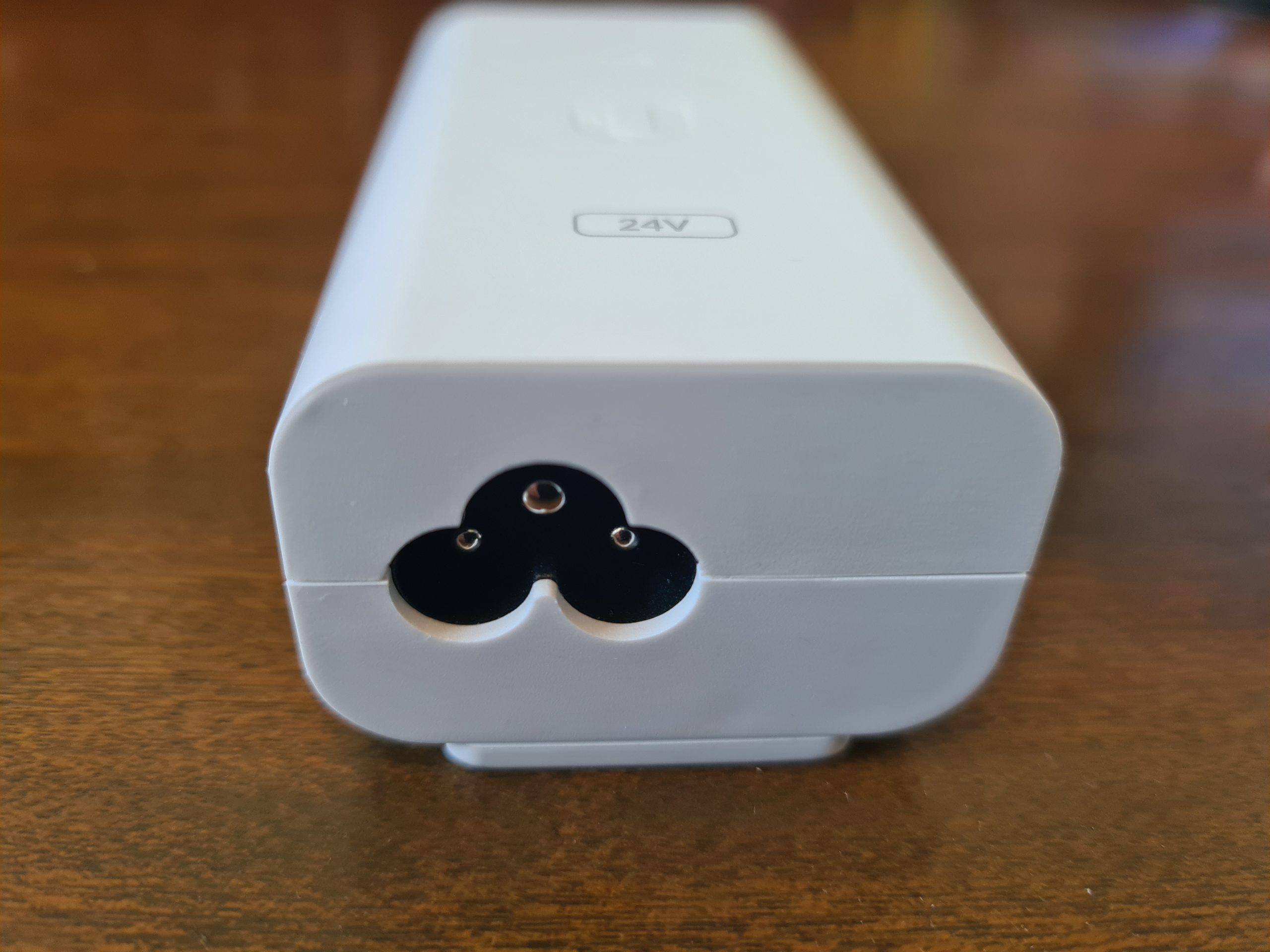
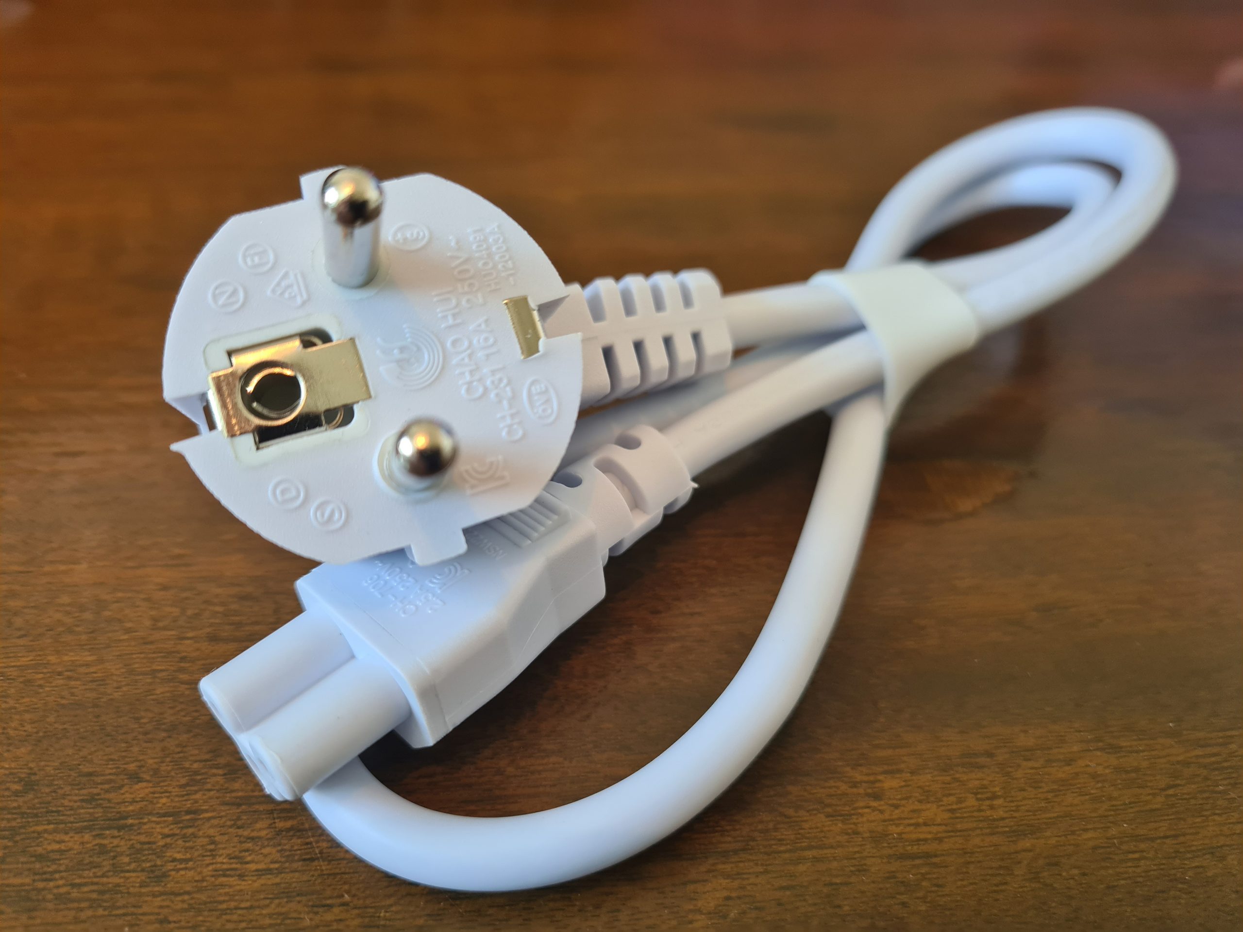
- USA Plug Adapter – Great if you’re USA based, but not so great if you’re UK Based. Thankfully our supplier for IT hardware equipment clearly has an arrangement in place with UniFi to supply a UK Based Plug for the device. Same UniFi branding / look / feel. Not sure if this is standard, but it’s just something to keep in mind when purchasing this IT hardware and equipment.
- UniFi Power over Ethernet (PoE) Device – This is the device that the above power adapter plugs into. This is potentially a device that you need. And this is because it depends if your managed switch supports PoE technology. Some devices support this heavily, others partially, and others simply don’t support PoE at all – hence why this device is often required in your setup. Personally I think that UniFi could significantly reduce the cost of their product by not shipping this device to their customers. A basic How-To guide for pre-purchase activities to enable customers to understand what they need to purchase under what circumstances would significantly help with this. I’d estimate that this would easily save £15 – £25 off the product cost if they were to implement a more structured purchasing process. Buy hey, I’ll leave that with them, if they want to reach our to me to discuss this business operational improvement then they are more than willing to do so.
- UniFi AP-AC-Lite Device itself – Kind of self-explanatory
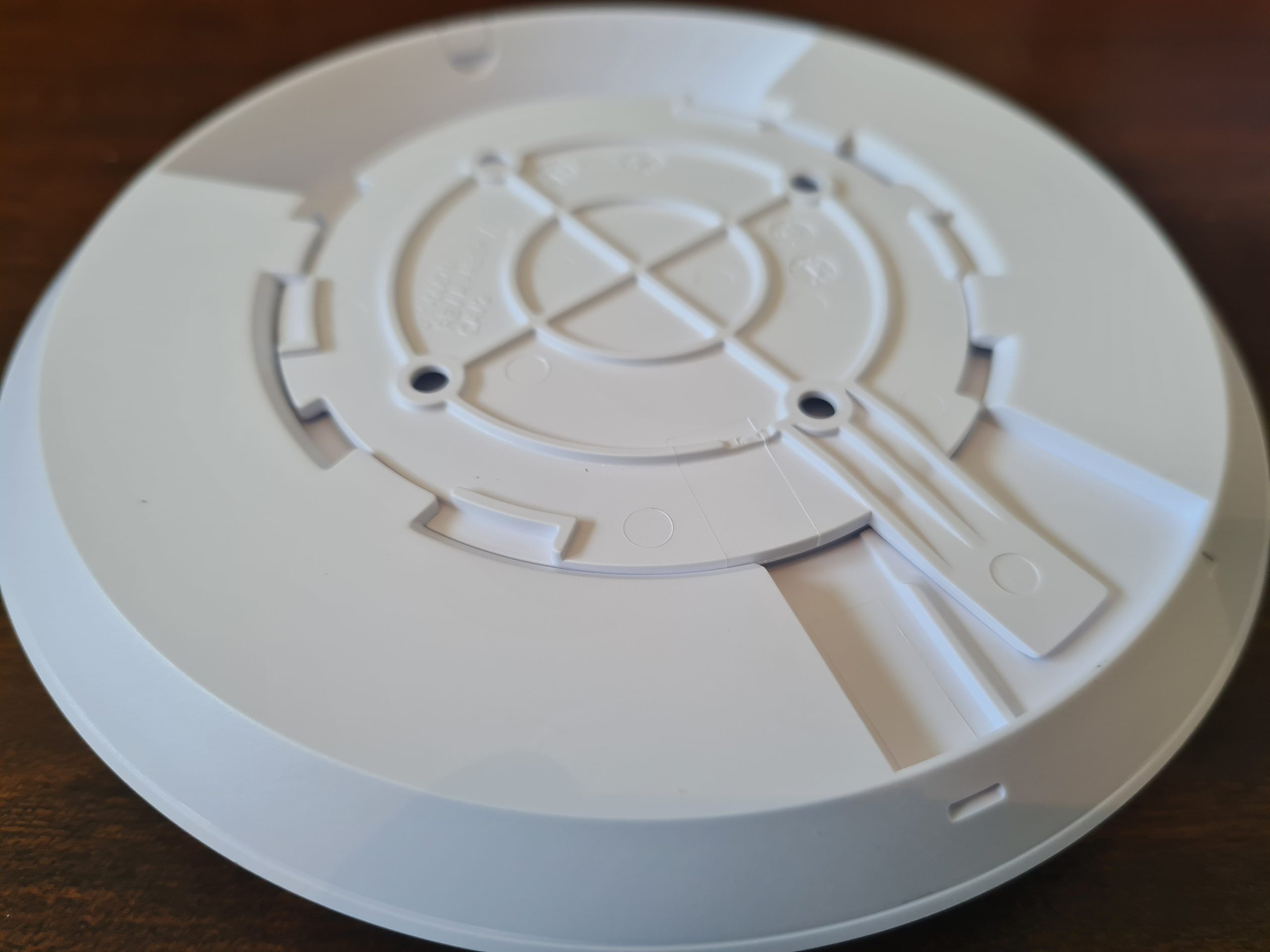
- Mounting Point – This is actually quite a nice device that let’s you easily secure your device to the wall or ceiling. As you’ll see later there is a handy detachable panel beneath the UniFi AP-AC-Lite access point that allows you easily connect this panel to the panel that attaches to the wall.
- Screws and Wall/Ceiling Plugs – Very handy so that you don’t have to source the specific sizes/lengths/width of screws and wall plugs to get the device attached to the location that you are looking to get this attached to. The reality is that these default screws are only a best guess, so it’s highly likely that you will need to source the specific screws and plugs that are relevant to where you are attaching the device to. But it’s a nice touch from Ubiquiti for common use cases.
Hardware Specifics
The Ubiquiti UniFi AP-AC-Lite Device;
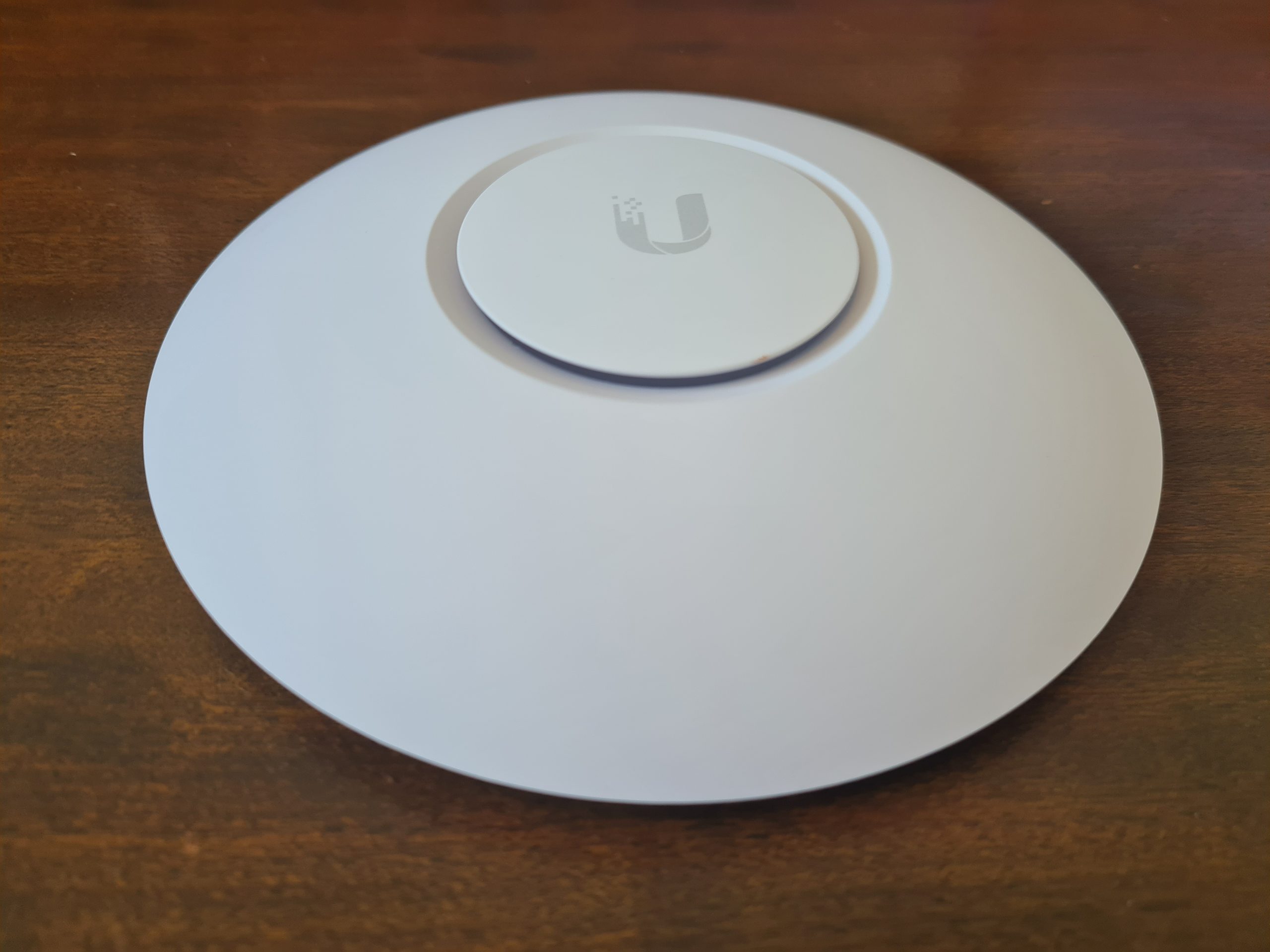
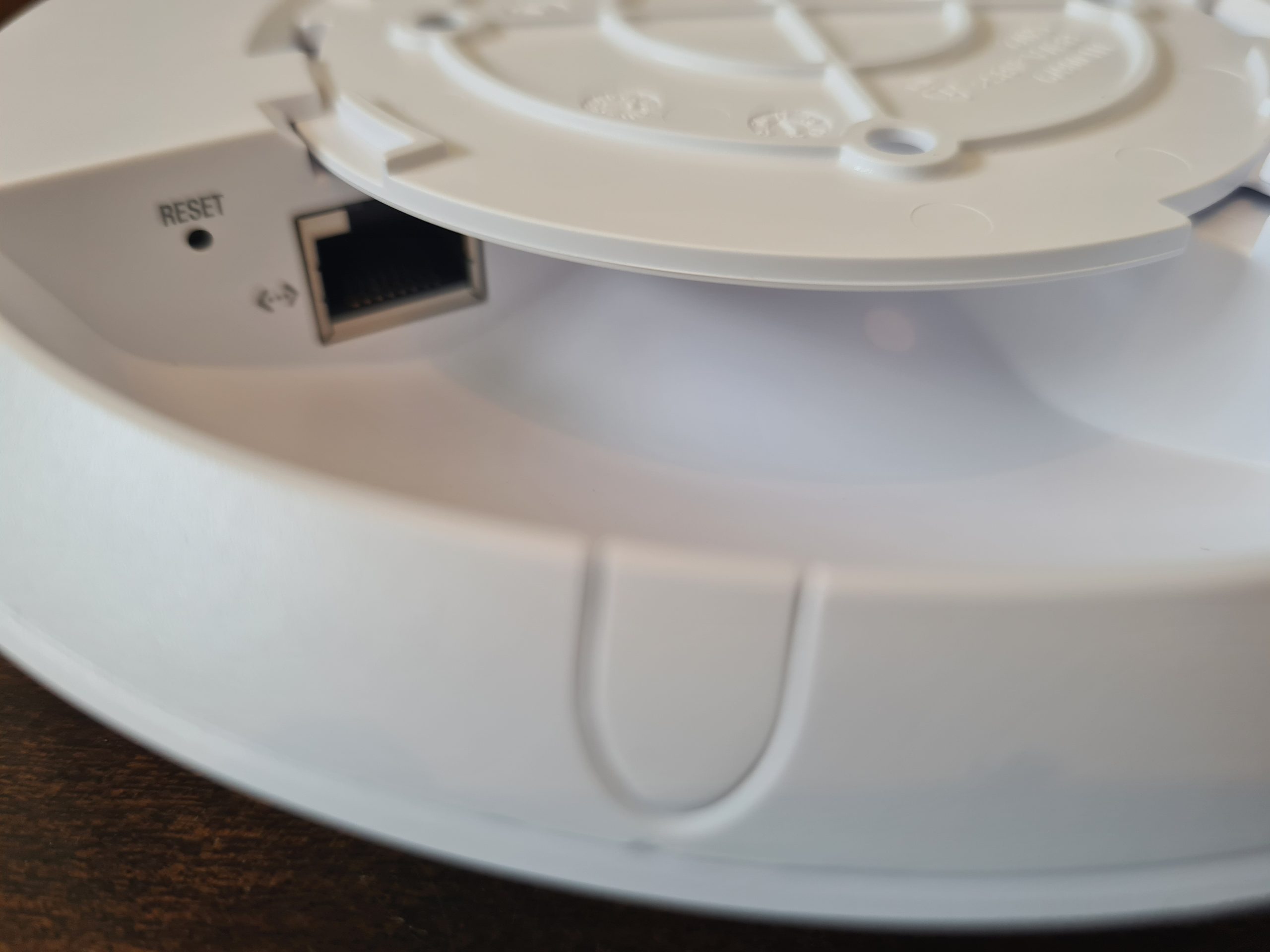
The device only has a single port and that is the RJ-45 port that allows you to connect the device to your network. And this is important as we briefly touched on earlier. This very much depends on if your network, or more importantly your managed switch, can support Power over Ethernet PoE technology or not. Depending on your answer to this question to yourself, you should be able to assess how this device is plugged into your network.
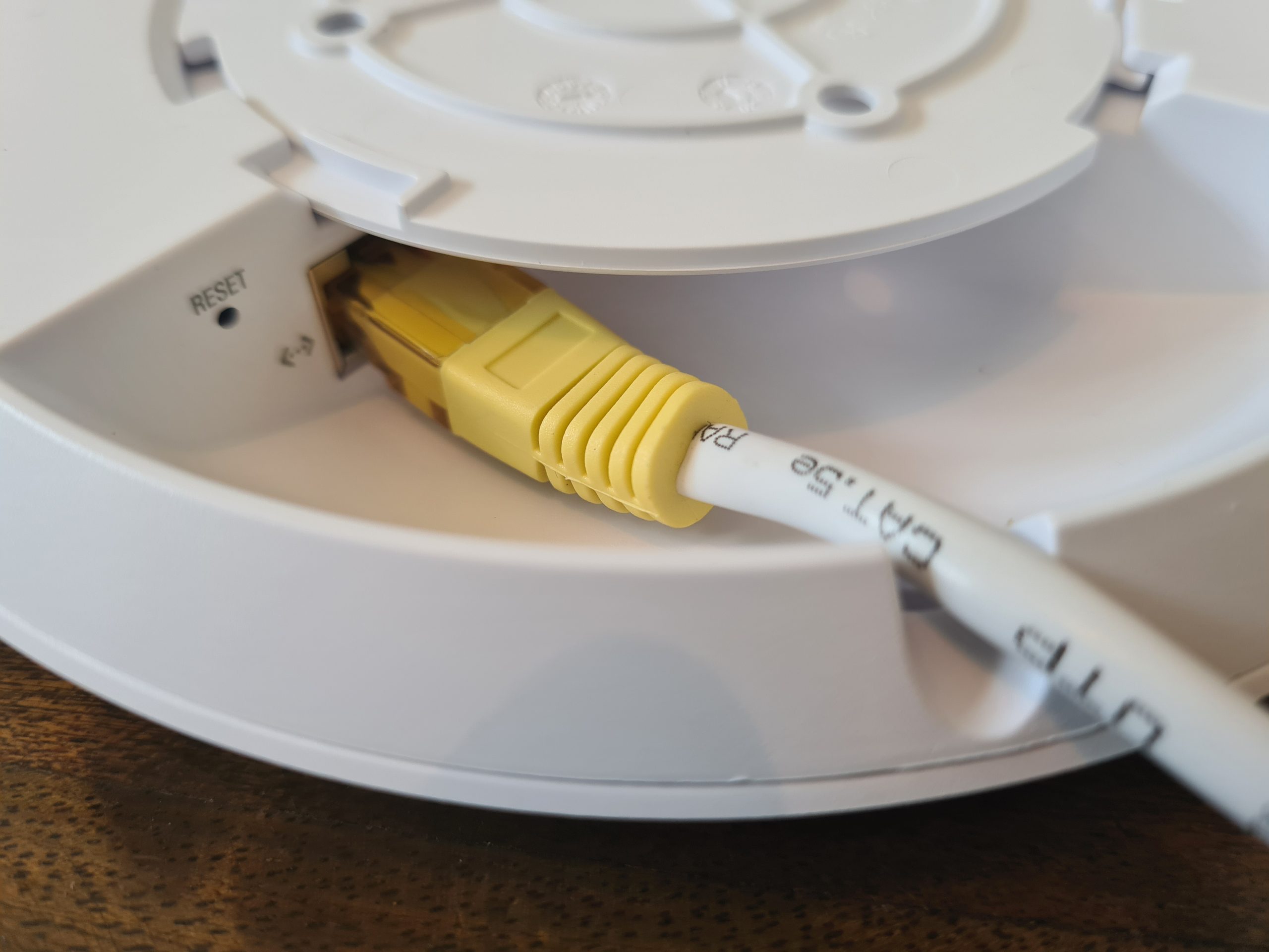
One handy feature is the small notch in the edge of the device that allows the ethernet cable to fit in the notch so the device can lay flat against your wall or ceiling.

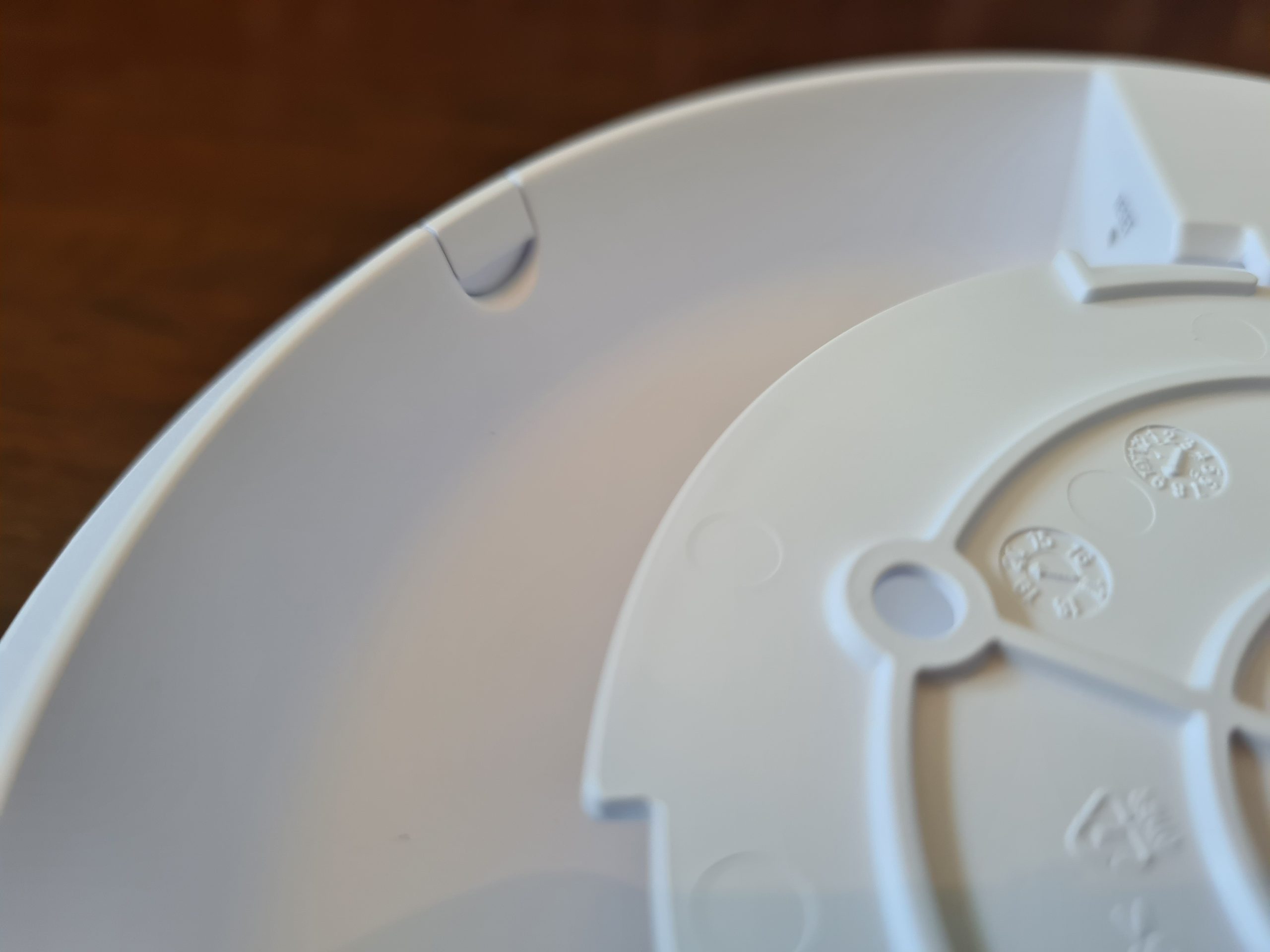
One item to note around how the inner disk connects to the main device is that once it is in place, it’s very tight to remove. When you are removing this when it isn’t wall mounted, this isn’t really an issue as you can easily get a small screwdriver or knife to unclip it. But you’ll notice that once this is connected to the wall or ceiling, you’ve only got a really tiny gap to get something in that is about 2mm tall, 5mm wide, and about 1cm deep – so you’ll probably need something like a paperclip to unhinge this once it’s connected to the wall.
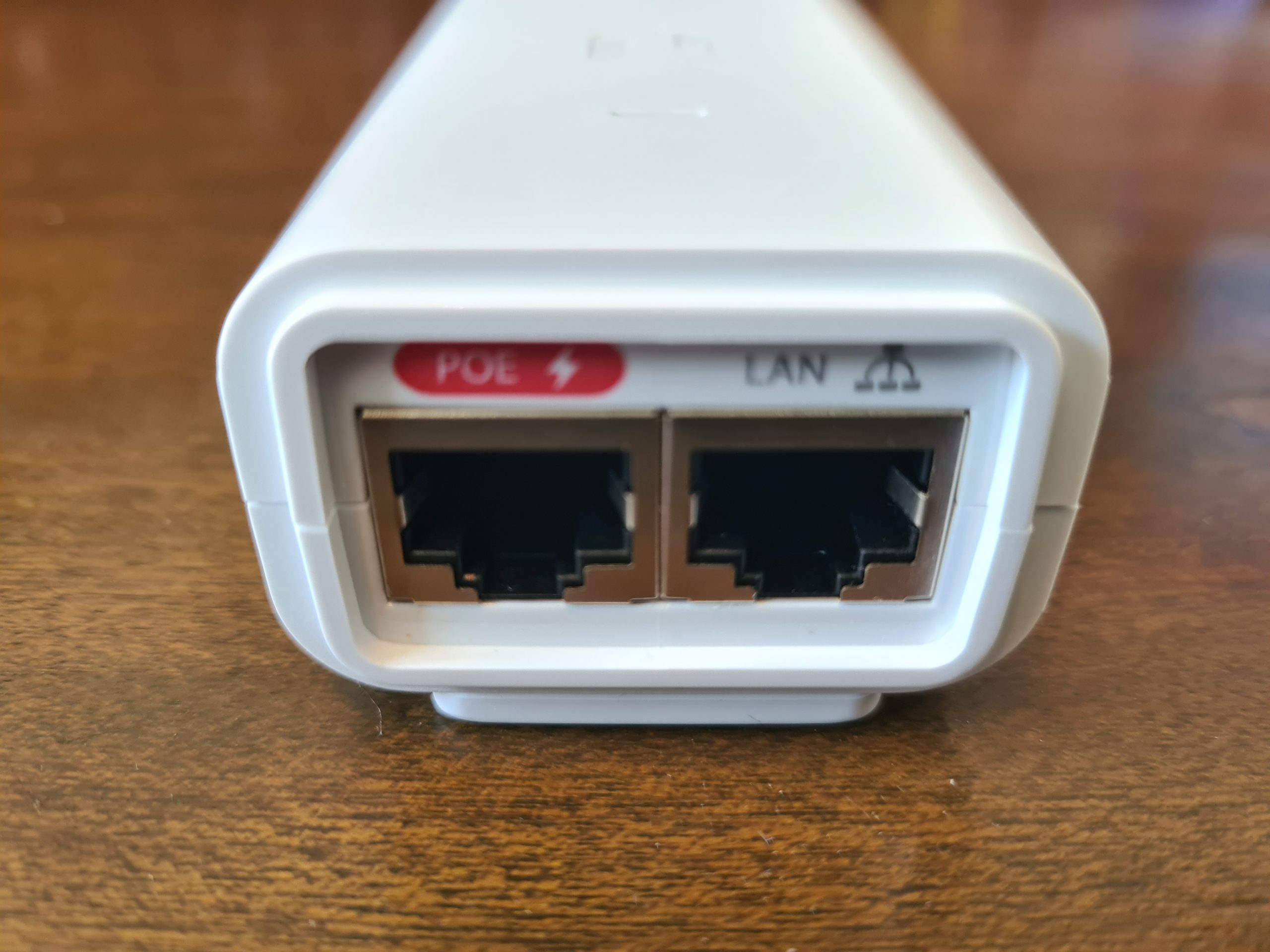
Below you’ll see the Power over Ethernet (PoE) device.
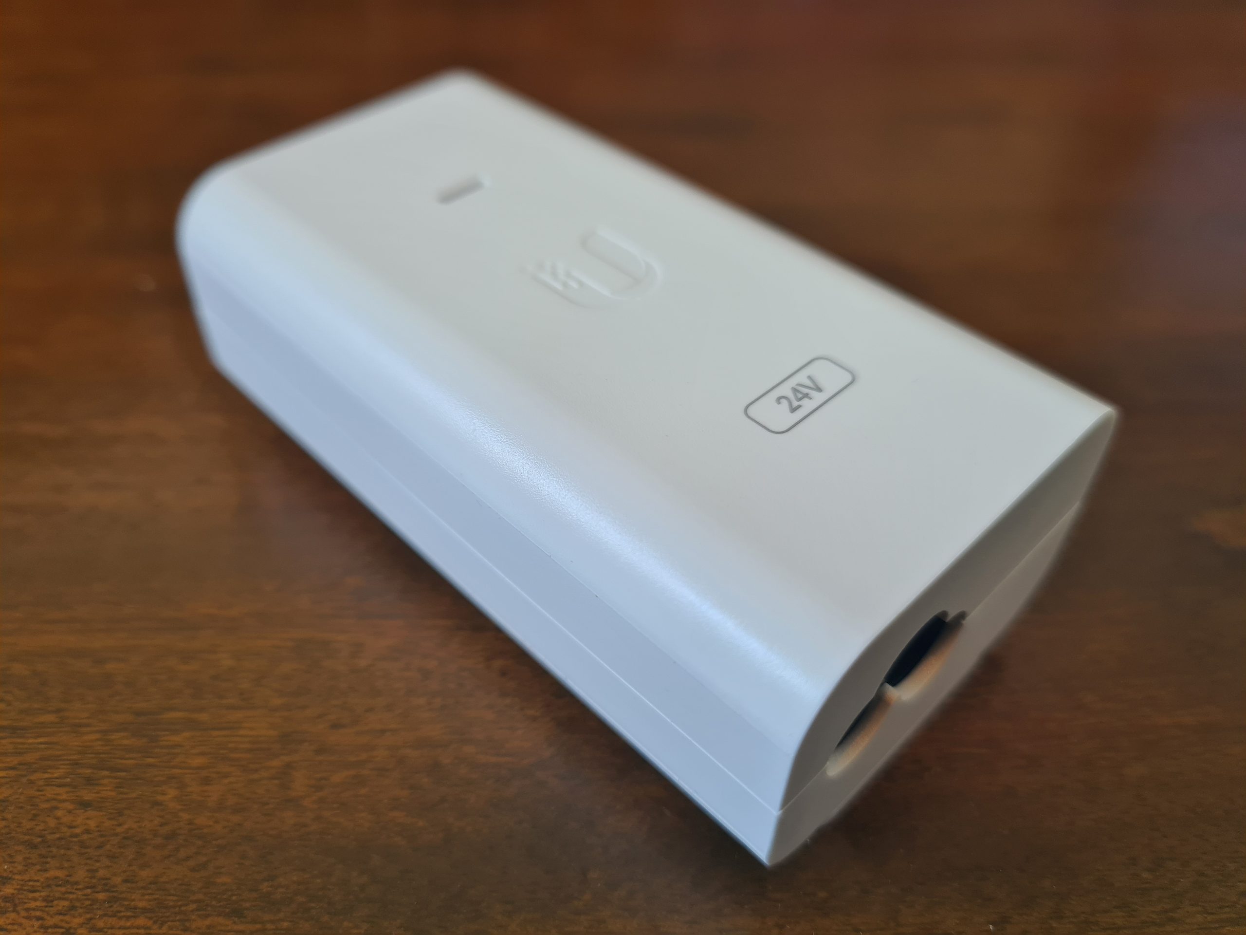
For connecting your PoE device to your UniFi AP-AC-Lite wireless access point, you’ll need to make sure you plug the ethernet cable into the PoE port on the left as that one contains power. The LAN port is where you plug in your ethernet cable that connects to your switch or router or firewall. If you have a managed switch with PoE ports, then you don’t even need to use this device unless you’re running our of power availability. But it’s nice that they have this as an option straight out of the box for you.
Another USA power lead going onto eBay…. 🙂
Ok, so that’s all the contents of the box for your new UniFi AP-AC-Lite wireless access point.
Statistics and Data from UniFi AP-AC-Lite Wireless Access Point via UniFi Controller
For completeness, let’s look at some of the handy bits of data that you can see within your UniFi Controller software against your wireless access point once you’ve got it plugged in and configured.
WiFi Traffic Distribution Statistics

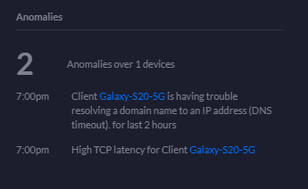
Anomalies Statistics
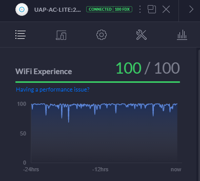
WiFi Experience Statistics
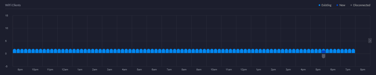
WiFi Clients Chart
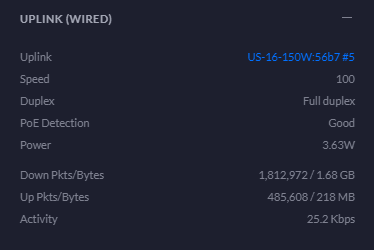
Uplink Statistics
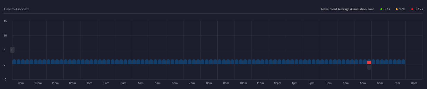
Time to Associate Graph
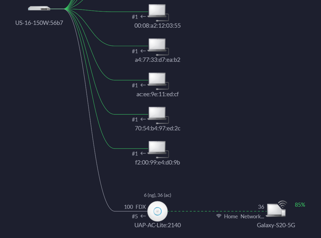
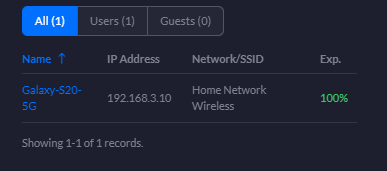
Showing Devices Connected to wireless access point
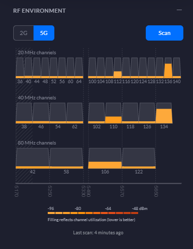
RF Environment 5G Statistics
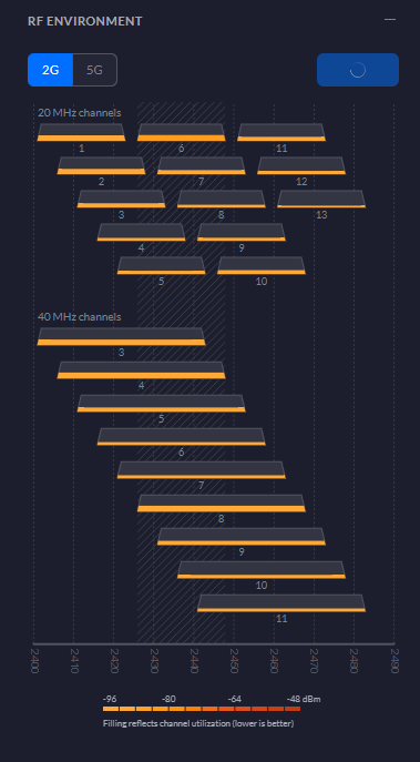
RF Environment 2G Statistics
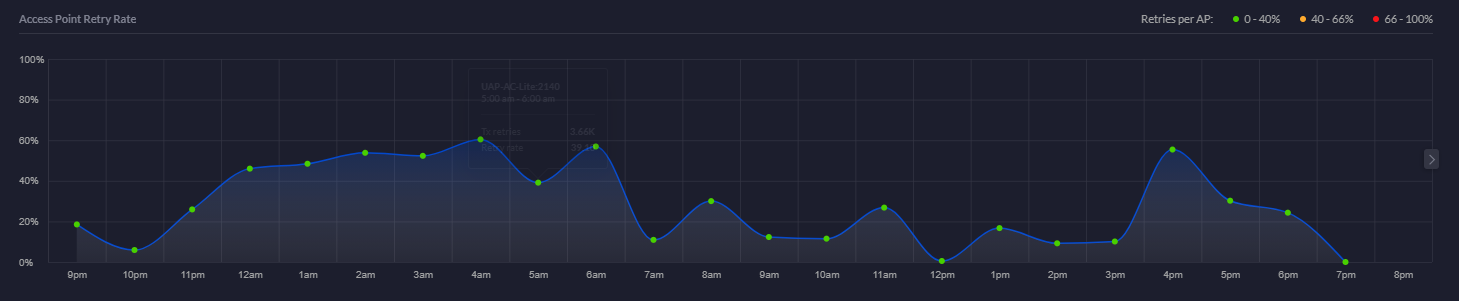
Access Point Retry Rate Chart
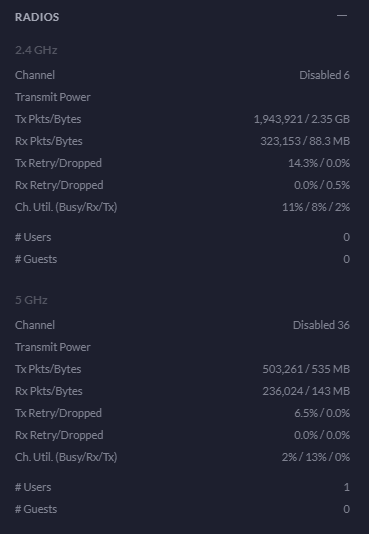
Radios Statistics
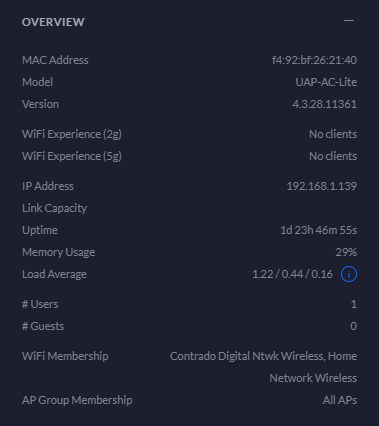
Overview Statistics
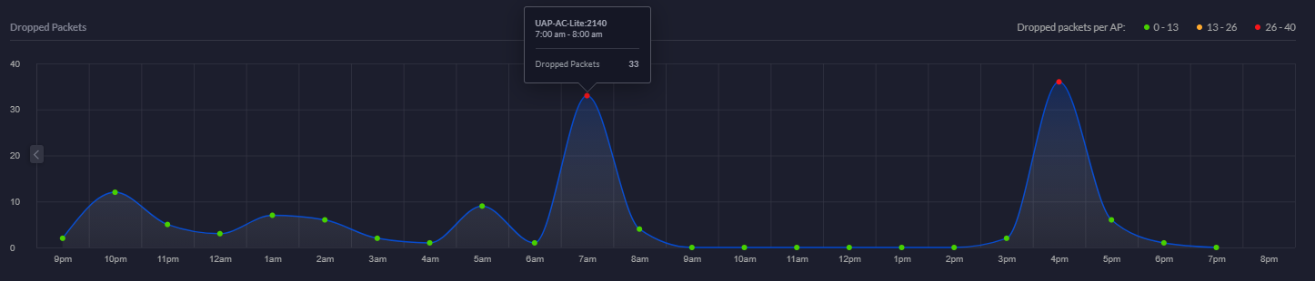
Dropped Packets Chart
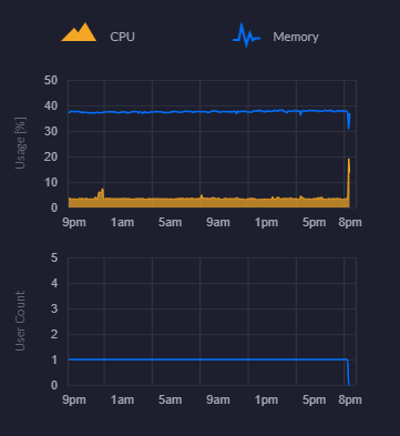
CPU and Memory Usage Chart
Connected Clients Statistics
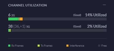
Channel Utilisation Statistics
This is a really handy piece of information from a planning perspective. You can easily use this information to plan your capacity based on real world usage. As you start to reach the higher limits of the hardware, it’s time to start planning an upgrade to hardware that is better suited to larger numbers of users. For context, the chart below is with a single mobile device connected.
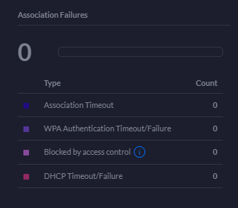
Association Failures Statistics
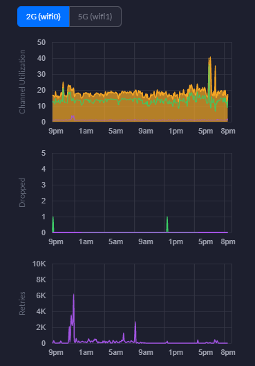
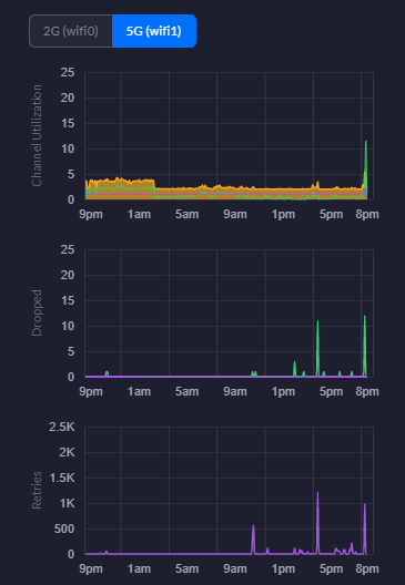
2G WiFi Charts – Channel Utilisation, Dropped Packets, Retries
5G WiFi Charts – Channel Utilisation, Dropped Packets, Retries
Hopefully that gives you a good idea about what’s in the box and what’s out of the box once you’ve got everything set up and configured within your network.
by Michael Cropper | Mar 12, 2021 | Client Friendly, IT, Networking |
In this blog post we’re going to look at how to setup a UniFi managed switch on your network. For simplicity and to help people get started we’re going to assume that this is the first managed switch you are looking to add into your network. We’re also going to assume you’ve got commercial grade modem and router hardware, none of the consumer grade stuff that just doesn’t really work for these types of commercial type setups.
Basic Network Architecture for a UniFi Managed Switch
Ok so let’s assume you’re new to all this networking malarkey, we’re going to take you through how to setup a Ubiquiti UniFi managed switch so you can adopt this on your network. For the purpose of this blog post we’re going to use a very basic base level architecture;
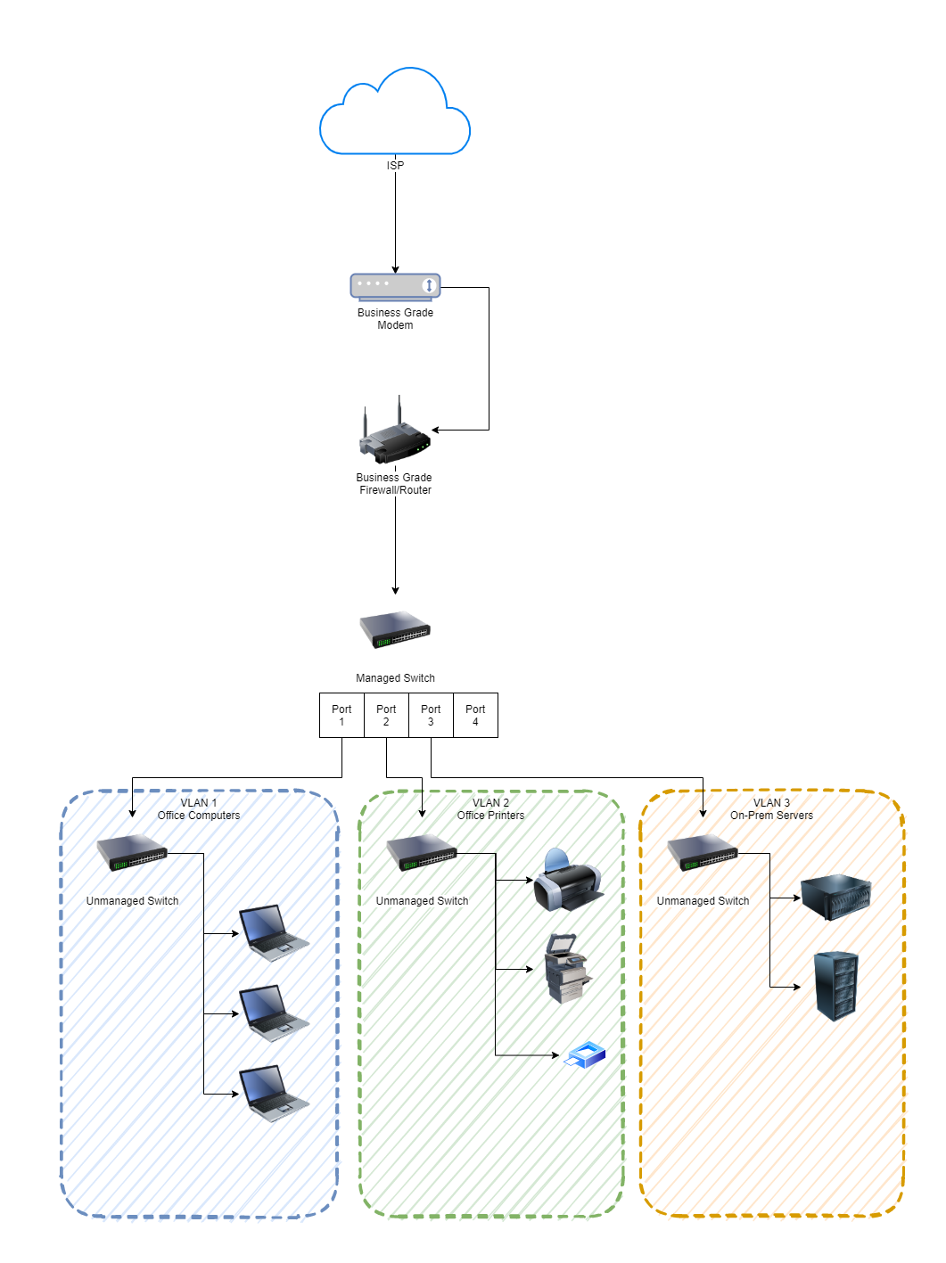
As you can see in the image above, the managed switch is bang in the centre. This is the Ubiquiti UniFi managed switch. Before we jump into how to get this set up and plugged into your network, if you aren’t sure about the differences, then we’ve done a blog post so you can easily understand What is the Difference Between a Managed Switch VS an Unmanaged Switch, have a read over that if you need a refresher.
Physical Ubiquiti UniFi Managed Switch Hardware
What we are working with here is basically this device;
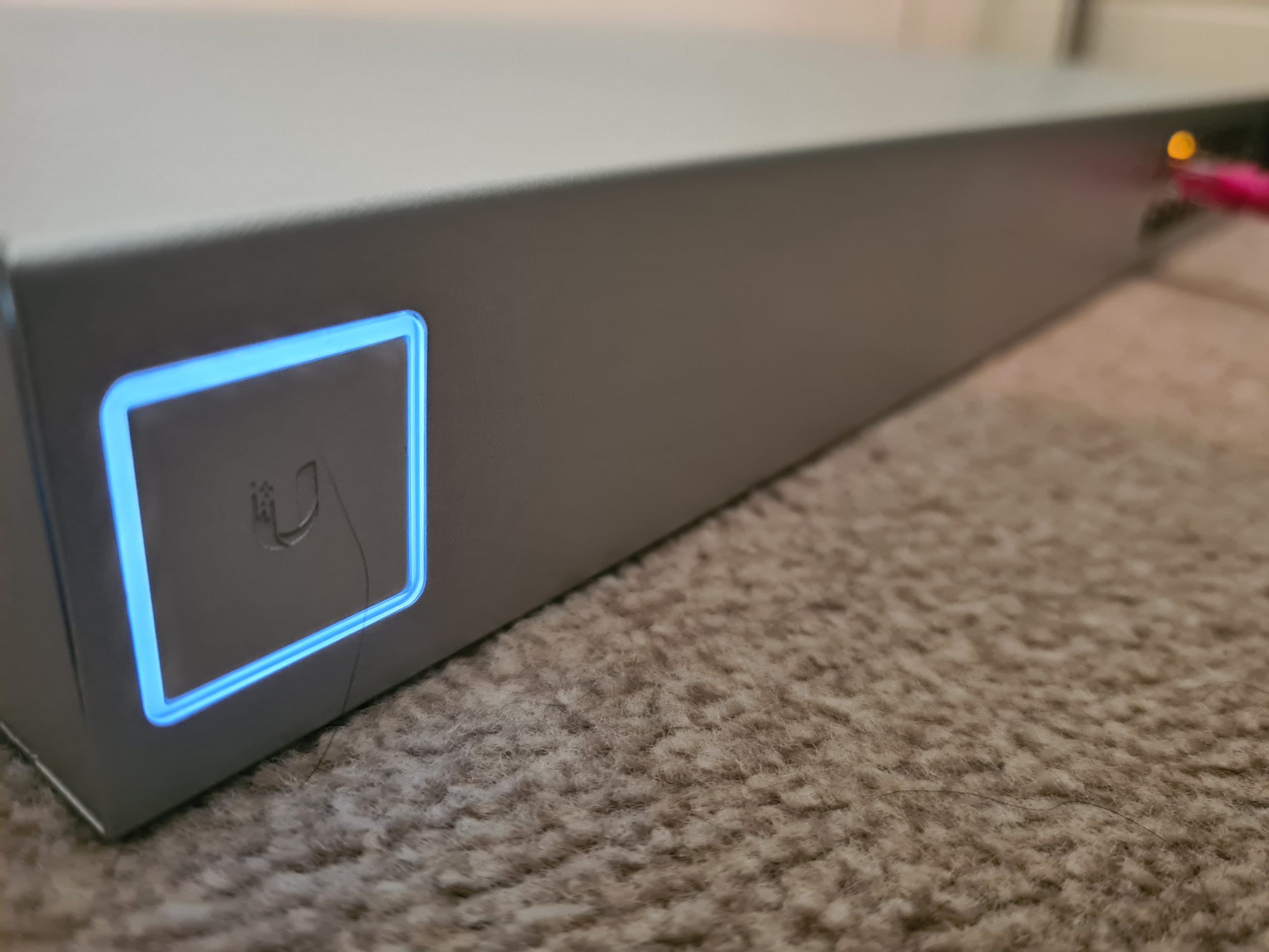
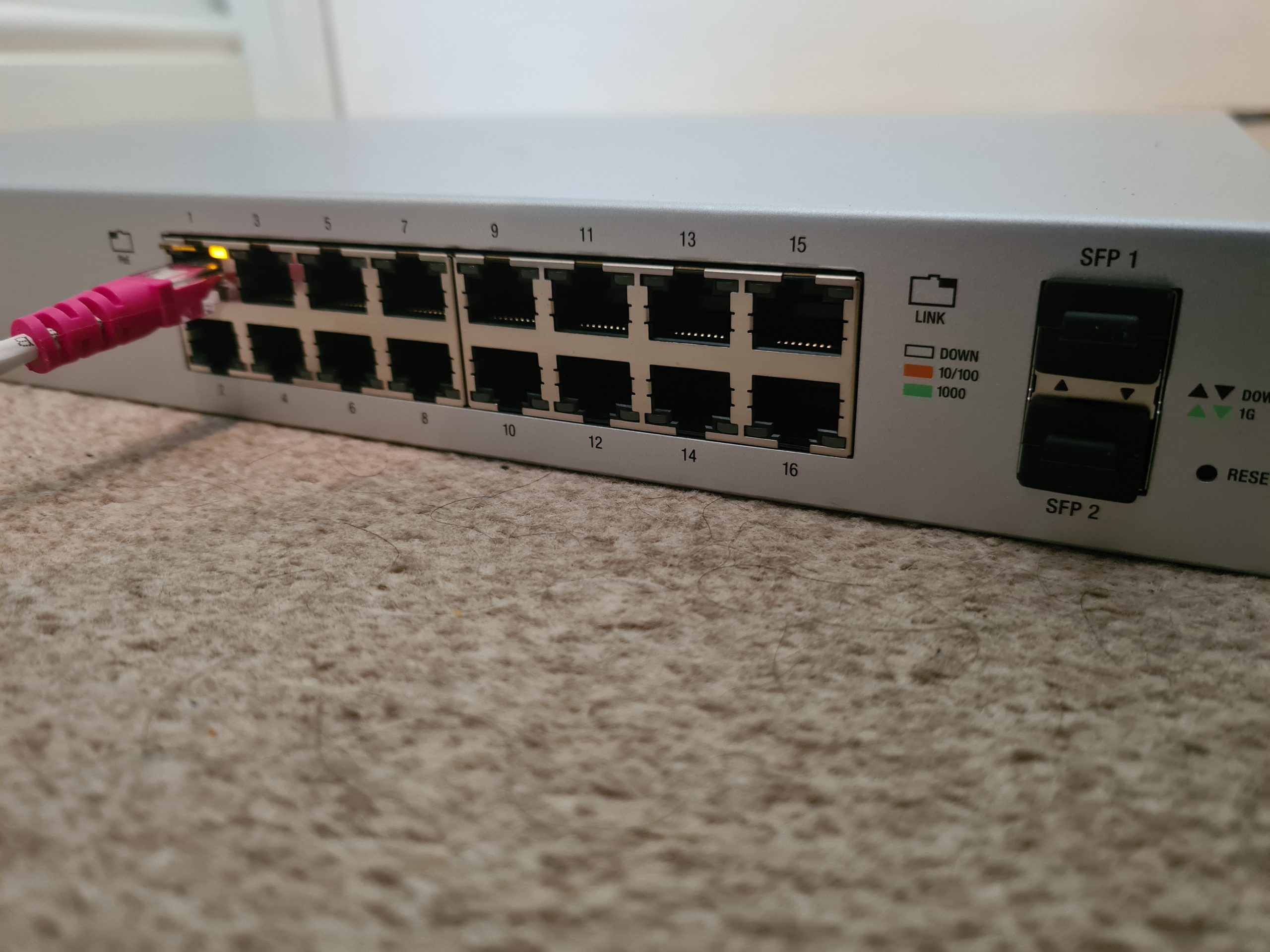
First of all, to get started simply plug the managed switch into your network. We’re assuming here that you’re currently working with a flat network so everything can see everything. You’re going to need to make sure you’re plugging the managed switch into the correct part of your network if you’re already got other managed switches and VLANs set up all over the place. But we’ll skip over that added complexity for the purpose of simplicity in this blog post.
Check UniFi Managed Switch is Showing in Firewall/Router
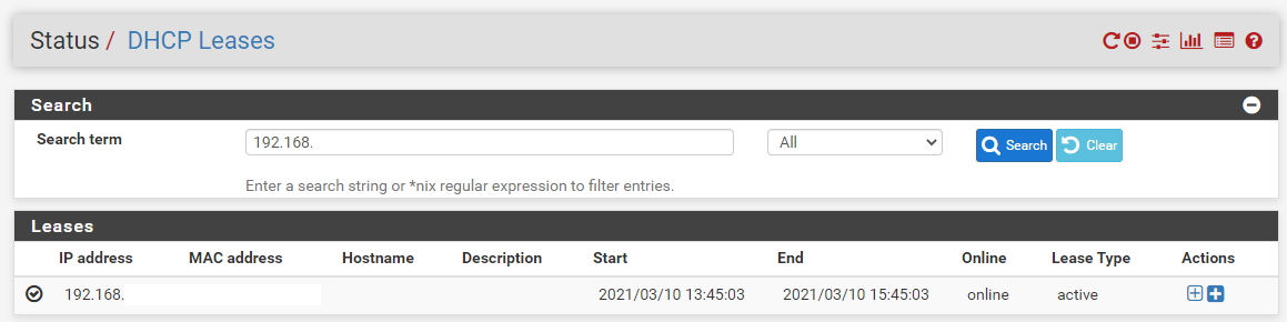
Ok, so now you’re plugged in, you need to head over to your Firewall/Router Admin screen and view the devices on the network. This is usually under a DHCP Leases type page within the admin interface. If you aren’t sure how to access your Firewall/Router admin interface, it’s highly likely to be either 192.168.0.1 or 192.168.1.1 which are fairly standard across a range of firewalls and routers. Simply type that into your web browser and you should be presented with a login screen. If you haven’t accessed this before (highly unlikely if you’re reading this blog post…. But for the purpose of completeness…) then just Google what the default username and password is for your specific device.
Once you’ve found the IP address of the device you’ve just added, excellent. You now know that the device is on the network;
Understanding the UniFi Controller Architecture
Now what is interesting with Ubiquiti UniFi managed switches is that if you type the IP address of your managed switch into the web browser, nothing happens. Nothing loads. And this is because the Ubiquiti UniFi hardware works differently than the vast majority of other networking hardware in the sense that we configure everything via an external piece of software called the Ubiquiti UniFi Controller. This is a piece of software that lives on a separate device such as your laptop or desktop computer. Here’s what this looks like to visualise how all this interacts;
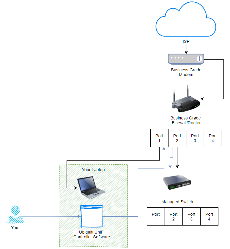
What we are looking at here, the black lines shows how everything is plugged in. The blue lines show how the process works for managing your UniFi managed switch. Pretty cool really, and this architecture of how all this works is one of the reasons that UniFi is completely blowing things away in the market with how there are designing and managing their networking hardware to make your life as easy as possible. Whether you are a small office/home office user or working up towards medium and large sized businesses. The Ubiquiti kit really is amazing.
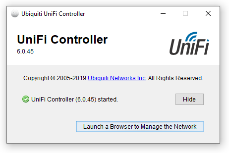
Install and Open UniFi Controller Software
Ok, so once you’ve downloaded the Ubiquiti UniFi Controller Software and installed it on your computer. Simply run the software (Windows Start Menu > Ubiquiti UniFi > UniFi);
Click the button to launch the site in the browser. If this is the first time you’re doing this, you’re going to need to go through the registration process. The browser will open the URL, https://localhost:8443/manage/account/login. You will get a certificate error but just ignore that if you are on a secure network, which it is highly likely that you will be if you are doing this type of work.
Once the web browser opens you will be presented with a login screen;
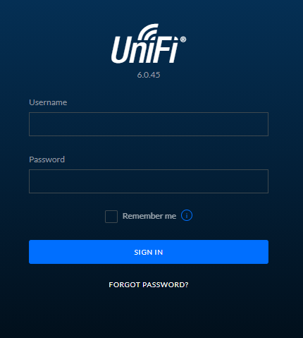
You’ll notice there isn’t a registration button here. If you don’t already have an account then you’ll need to create a Ubiquiti UniFi account here, https://account.ui.com/register. Once you’ve created your account, you will then be able to login to your device. For the purpose of simplicity in this blog post, we are going to assume that you are not using a UniFi Cloud Key. First of all, the UniFi Cloud Keys are an awesome piece of tech that allows you to easily manage your network completely remotely. This comes in extremely handy for IT managed service providers like ourselves who manage the network infrastructure on behalf of clients. We’ll cover that off in a different topic though at a later date.
View Current UniFi Network
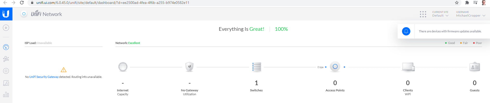
Once you’re logged in you will land on the dashboard;
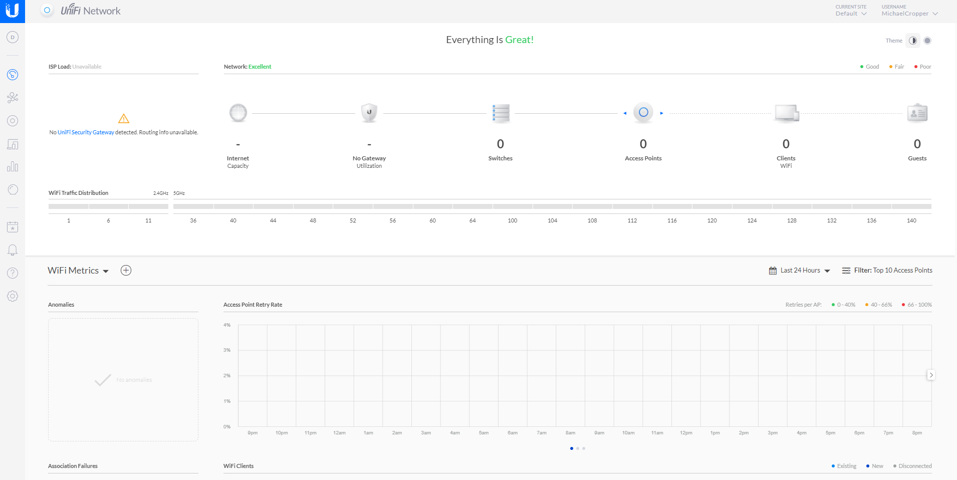
You’ll notice in the picture above that there is nothing there, you have no UniFi devices on your network. Sounds odd at first since you have your UniFi managed switch plugged in, but there is a reason why it is not showing up in your network yet and we’ll look at that now.
Adopt UniFi Managed Switch to Your Network
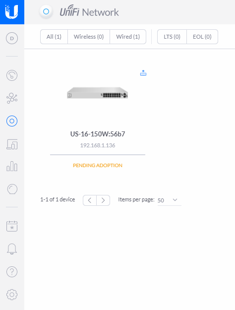
Firstly, you know you’ve just plugged in a UniFi managed switch into you network, so let’s click on the Switches icon;
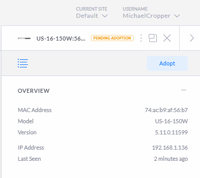
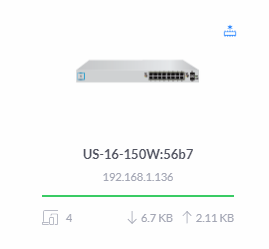
What you’ll notice when you click into that page is that the UniFi managed switch is now showing, but it is showing at the Pending Adoption stage;
Device Adoption is simply the process of connecting a UniFi device to your UniFi Controller Software so that you can manage it accordingly. You can read more about that here if you are interested. Just before we jump into adopting the device. A couple of nice little features within the UniFi dashboard are worth pointing out. Firstly, the Events button in the left navigation, the one that looks like a calendar icon with an * in the middle. Here you can see the exact date and time you plugged the UniFi managed switch into your network;
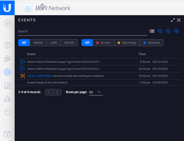
The fact that the software has automatically detected this and logged this event is pretty awesome, particularly for both auditing and debugging purposes. The one of the core benefits of the UniFi Controller Software is to ensure you can’t just go plugging hardware into your network and having that hardware automatically work. The UniFi platform can help to protect you from that attack vector.
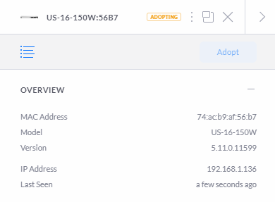
So back to the previous image. Click on the managed switch that is pending adoption. You’ll notice a pop out appear;
Then you will see that the managed switch moves through to the Adopting stage, this means that the managed switch is being adopted by your UniFi Controller Software so that it can be managed;
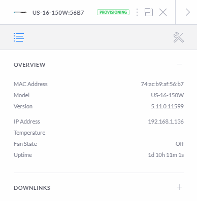
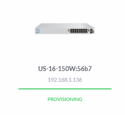
Next you will see the status move through to the Provisioning status. The provisioning status means that the device is in the process of applying updates and/or changes to the configuration and will temporarily reboot so the changes take effect. In this specific example, this makes no real difference as you are just getting setup but in any real world scenario this can result in a momentary blip in the connectivity for your users. Depending on your wider network configuration, you may need to schedule these types of activities to happen at times of low network activity. This is a very difficult thing to balance in corporate environments as you’ll generally find that backups and similar activities are also happening at off-peak times so you really need to fully understand your network and infrastructure architecture at all levels to be able to safely perform these activities. Otherwise, you’re just acting on a “click and hope” mentality. For a single managed switch setup that we’re working through here, this is not really an issue either way. But for larger networks you really need to understand which configuration changes have propagated through to each and every device on the network. If you are getting issues with provisioning configuration settings on specific devices this is really going to screw with your network and cause lots of random problems all over the place.
Once this is complete, you’ll start to see your devices listed as being in the Connected status;
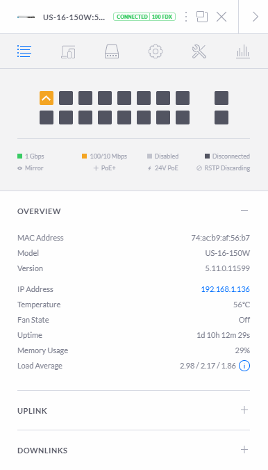
What is interesting in the image above is that you’ll notice that this port diagram exactly represents the port connectivity in the photograph from the very start of this blog posts that shows you how you have connected your physical UniFi managed switch into your network. This is showing you your physically connected ports in a digital view to help you visualise what is currently connected and what availability you have for future planning. While not that relevant for this blog post, it’s worth noting that this is a very handy feature particularly for larger networks spanning multiple geographical locations, knowing what is plugged in where and how this is all configured is extremely valuable so you can plan for future growth and projects as your networking needs expand.
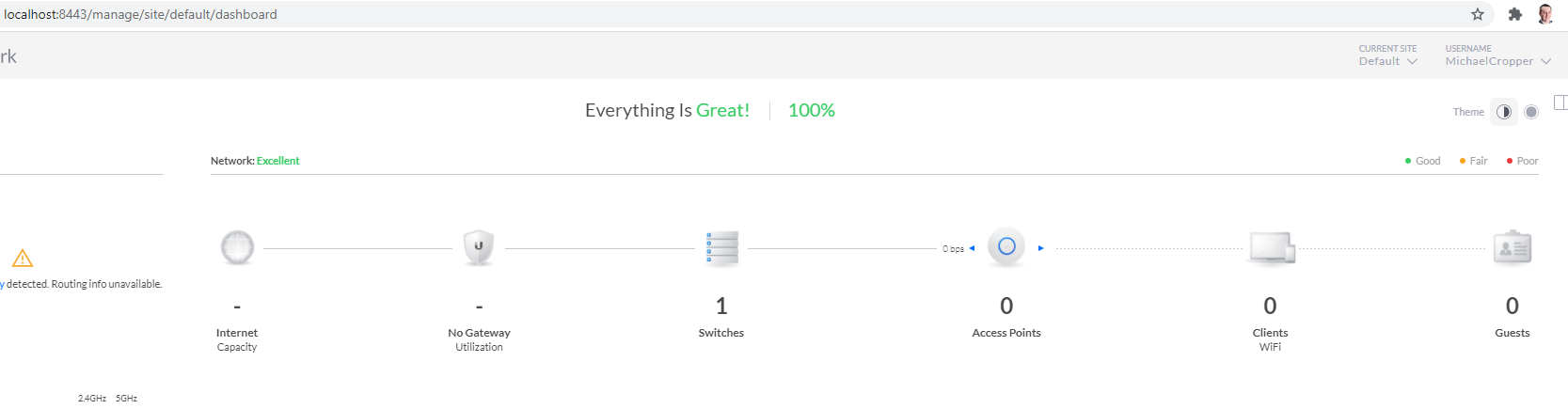
Once you’ve done you’ll notice that your network on your dashboard now looks like the following;
UniFi Cloud Connectivity
What is interesting once you’ve logged into your local UniFi Controller Software locally is that if you view your UniFi account on the UniFi website, you’ll notice the exact same details listed. This is extremely handy to see what is happening on your local network from anywhere in the world. The reality is though is that this functionality is only
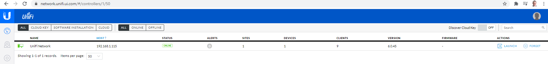
In the above image you’ll notice a “Launch” action on the right hand side. What this does is it enables a connection from the UniFi cloud platform straight through to the computer that is running the UniFi Controller Software. Generally these things are powered by the powerful UPnP (Universal Plug and Play) Protocol. I’ve not dug into the details of how this specifically works for the UniFi kit, but I’m going to take an educated guess that it is highly likely that it is UPnP that is powering this functionality. Either way, awesome, as this is a cool piece of tech.
This functionality is basically what the UniFi Cloud Key does, the only difference being that the UniFi Controller Software doesn’t need to be running on your laptop, but instead there is basically a RaspberryPi-like device plugged into the network to perform this feature. The UniFi Cloud Key is actually very similar to how one of the products we’ve designed and built works, the GeezerCloud platform which monitors temperature controlled environments remotely with ease for companies including restaurants and food manufacturing businesses.
Back to looping at the specifics of the UniFi Cloud Platform and how this works though. Once you have clicked on the Launch option, you’ll notice that the UniFi cloud platform is completely aware of your local UniFi network as you have seen in previous images – the only difference is the URL that you are accessing this information from. If you understand what this means, you’ve probably got your eyes raised too as you realise how amazing this feature is. If you don’t understand what this means, add 10+ years to your career and it will sink in why this is so awesome – Apologies on that point but it is difficult at times to convey breakthrough moments in technology like this without understanding the technology stack in a serious way both wide and deep, that stuff only comes with years of experience and knowledge and can’t be easily conveyed in a basic blog post – but – if you have questions, do put them in the comments on this blog post to get the answers you seek.
Back again to once you’ve clicked that Launch button mentioned earlier. What you’ll notice is that once you’ve clicked that, the URL is on the UniFi Cloud Platform, yet it is displaying information from your local network exactly as if you were viewing the information via your locally installed UniFi Controller Software;
All Connected Now Time to Configure
Awesome, now your managed switch is part of your network you are good to start to configure it in the way you like. We’re going to stop this blog post here as the configuration elements of a network can get very detailed so we’ll pick that up in a future blog post.
There are so many different ways to configure your UniFi managed switch that this all depends on the entire network architecture and devices (both UniFi and non-UniFi) that you are working with throughout your network.
Summary
Hopefully this has been a useful insight and tutorial on how to set up a Ubiquiti UniFi managed switch on your network. This guide has been focused on a starting point from nothing, so if you are working with an established network, very similar principles apply, although you’ll need to take extra precaution and understanding of the wider network piece before randomly plugging an additional managed switch into your network.