by Michael Cropper | Feb 8, 2023 | Developer |
Note: This blog post is entirely generated by AI with the prompt “Write a blog post titled “What is Docker” which is around 2000 words in length and include sub-headings to make the content easy to read. ” ….. Leave a comment on what you think…..
Docker is an open-source platform that automates the deployment, scaling, and management of applications inside containers. In simple terms, it provides a way for developers to package their applications and dependencies into a container, which can then run consistently on any system that has Docker installed.
Containers vs Virtual Machines
One of the key differences between Docker and traditional virtualization methods like Virtual Machines (VMs) is that containers share the host system’s operating system (OS) kernel, while VMs run on a full copy of the host’s OS. This makes containers much lighter and more efficient than VMs, as they don’t require the same amount of system resources or disk space.
Another important difference is that containers are isolated from one another, but share the host’s OS. This means that each container runs its own application and dependencies, but they are all running on the same underlying system. In contrast, VMs are completely isolated from one another and run their own OS, which can lead to compatibility issues between different systems.
Why use Docker?
Docker provides several benefits over traditional virtualization methods:
- Portability: Docker containers can run on any system that has Docker installed, making it easy to move applications between development, testing, and production environments.
- Scalability: Docker makes it easy to scale applications by adding or removing containers as needed, without having to reconfigure the underlying system.
- Isolation: Each Docker container runs in its own isolated environment, which helps to ensure that applications don’t interfere with one another.
- Consistency: Docker ensures that applications run consistently across different systems, as they are packaged with all of their dependencies.
- Ease of use: Docker provides a simple and straightforward way to manage containers, making it easy for developers to focus on writing code instead of dealing with complex infrastructure.
Docker Architecture
Docker uses a client-server architecture, with the Docker client communicating with the Docker daemon, which is responsible for building, running, and managing containers.
The Docker client and daemon can run on the same system, or they can communicate over a network. The Docker client sends commands to the Docker daemon, which then performs the requested actions.
Docker Hub
Docker Hub is a public repository for Docker images, which are pre-built packages that include everything needed to run a specific application or service.
Developers can use images from Docker Hub to quickly get started with building and deploying their applications, or they can build their own images and upload them to Docker Hub for others to use.
Dockerfile
A Dockerfile is a script that contains instructions for building a Docker image. It specifies the base image to use, the application and dependencies to include, and any configuration information that the image needs.
Once the Dockerfile has been created, developers can use the Docker build command to build the image and create a container from it.
Getting Started with Docker
Getting started with Docker is straightforward, as it only requires a few basic steps:
- Install Docker: To start using Docker, you’ll need to install it on your system. Docker is available for a wide range of platforms, including Windows, macOS, and various Linux distributions.
- Download a Docker image: You can either download a pre-built image from Docker Hub or build your own image using a Dockerfile.
- Run a container: Once you have an image, you can use the Docker run command to create a container from it and start it running.
Conclusion
Docker is a powerful platform that makes it easy to
Commentary on my opinion of the quality of the ChatGPT generated blog post
Honestly….. Not bad. Technically accurate too. But….. It’s only ~500 words in length, the content is very surface level and nothing really makes sense unless you know this stuff already which kind of makes it a bit pointless. The challenge here is that these topics are complex, the documentation is complex, there are lots of moving parts and actually the whole benefit to writing blog posts is not to write a high level overview of the topic, but to help readers truly understand so they can anchor their existing knowledge towards a new topic so they can get up to speed quickly.
Very gimmicky, entertaining but when it comes to something I would deem as high quality, it’s a long way off. I do like the headings it introduced though (formatted manually), but in reality, nothing that you can’t easily create the structure of a blog post with a tiny bit of research on the topic before jumping straight in.
by Michael Cropper | Jan 9, 2023 | IT, Technical |
This is a topic that comes up quite infrequently for many people and for most, never. It’s also one of the topics that is significantly more complex than it should be and one that is fairly poorly documented online about how to do this properly. Fundamentally this is a basic Copy & Paste exercise at best, but it’s made ridiculously complex by the underlying technical gubbins. So hopefully this blog post can clear up the steps involved and some of the considerations you need to make.
Old and New Disks
Disks come in many different shapes and sizes both conceptually and physically, with varying connectors and different underlying technologies. The nuances of these are beyond the scope of this blog post, but to put a few basics down to help conversation let’s look at a few of these at a high level.
We’ve previously covered off topics on the Performance of SSDs VS HDDs so take a look at that for some handy background info.
Summary being that you essentially have two types of hard drives;
- Mechanical Hard Disk Drive (HDD) – Has moving parts
- Solid State Drives (SSD) – Has no moving parts
See the above blog post for further insights into the differences.
Anyhow, the important point being for the purpose of cloning a hard disk is that you need to know the details of what you are going from and what you are moving to. Get this wrong and you can seriously mess things up in a completely un-recoverable way, so please be careful and if you aren’t sure what you are doing, don’t proceed and instead pass this onto a professional to do this for you.
Disk Connectors – IDE VS SATA
For the sake of simplicity, the two core connectors for disk drives fundamentally fall into either IDE (old) and SATA (new). Yes, the teckies who are reading this will say that this is garbage, and it is. But, in reality, for those reading this blog post, this is likely going to cover 99% of the use case.
In reality there are many types of disk connectors from PATA, SATA, SCSI, SSD, HDD, IDE, M.2 NVMe. M.2 SATA, mSATA, RAID, Host Bus Adapters (HBA) and more (and yes, not all of these are technically connectors… but for the sake of simplicity, we don’t care for this blog post). At the time of writing, the majority of people using the many other various types of disk connectors outside of the basics are generally going to be working within corporate enterprises which tend to operate on a bin and replace mentality from a hardware perspective for basic user computers and for data centres and server racks have setup with cloud native data storage with high availability and lots of redundancy. For many smaller organisations and/or personal use case, this is a goal to work towards.
Which is why we are covering this topic for the average user to help to understand the basics for how to clone a hard disk either if you are upgrading and/or are trying to recover data from a failing disk.
Adapters
Ok, so we’ve covered off the different types of hard disks, it’s time to look at how we connect them to a computer to perform the data migration. Here is where we need the correct connectors to do the job, and this isn’t straight forward.
For simplicity and ease, USB is likely to be the easiest solution for the majority of use cases. Note there is a significant difference in USB 1.0 VS USB 2.0 VS USB 3.0 when it comes to performance and to add to the complexity, there are also different USB Form Factors (aka. different shapes of the connector, but fundamentally doing the same thing) which adds to the confusion.
I work in this field, and I am continually surprised (aka. annoyed…) by the manufacturers who continually make this 1000x more complex than it needs to be. I for one am extremely happy that the European Union (EU) has decided to take a first stance on this topic to help to simplify the needless complexity by standardising on a single port type for charging devices. Personally I have endless converters, adapters, port changers, extender cables and more for the most basic of tasks. It’s a bloody nightmare on a personal level. And at an environmental level, just utterly wasteful.
Anyhow, to keep things simple again, there are a few basic adapters you probably need to help you with cloning a hard disk. These are;
- USB External SATA Disk Drive Connector / Adapter Cable (buy here)
- USB External SATA, 3.5” IDE, 2.5” IDE Disk Drive Adapter Tool Kit (buy here)
Connectors, Adapters and Speed
This is a complex topic, and one that quite frankly I don’t have the time to get into the details of – mainly because the manufacturers don’t make this easy and/or make this far more difficult than it should be. You see, we have things such as USB 1, 2, 3, SATA 1, 2, 3, IDE, 1, 2, 3 etc. and I just don’t have the mental capacity to care about too much the differences between these things. I work with what is available and adapt as needed.
The reality is that each and every connector or adapter has a maximum data transfer rate based on the physical materials and hardware that the device has been manufactured from. Everything has limitations and manufacturers don’t make this info easily accessible and/or understandable to the average joe.
Unique IDs of Disk Drives
Right, so now we’re onto the actual hard disk data migration. Now things get fun, and possibly dangerous – so be careful.
Almost every guide I’ve read online skims over this really important point, and it’s probably the most crucial point to take into account – which is to know your IDs, your Unique Hardware Identifier.
For a bit of background as it’s important to understand. For those with a software engineering and/or database background, you will be very familiar with a Unique Identifier for a ‘thing’. Well, with hardware manufacturing, they also do the same thing. For every physical chip that is manufactured, this is generally embedded with a hard coded unique identifier which both helps, and hinders, in many different ways, but that is a topic for another discussion. For example, the sensors that we use on the GeezerCloud product have a Unique ID for every single sensor that we use.
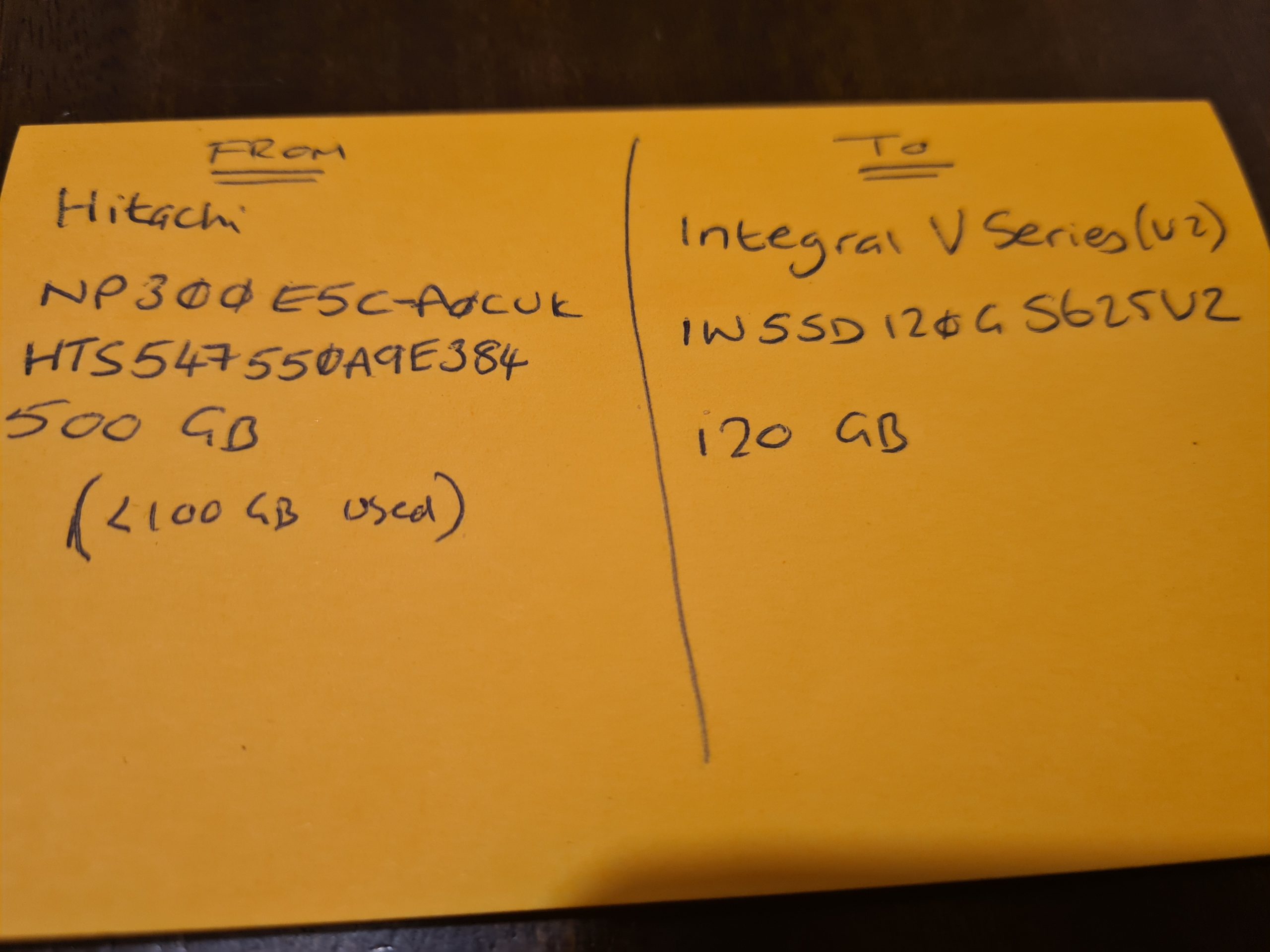
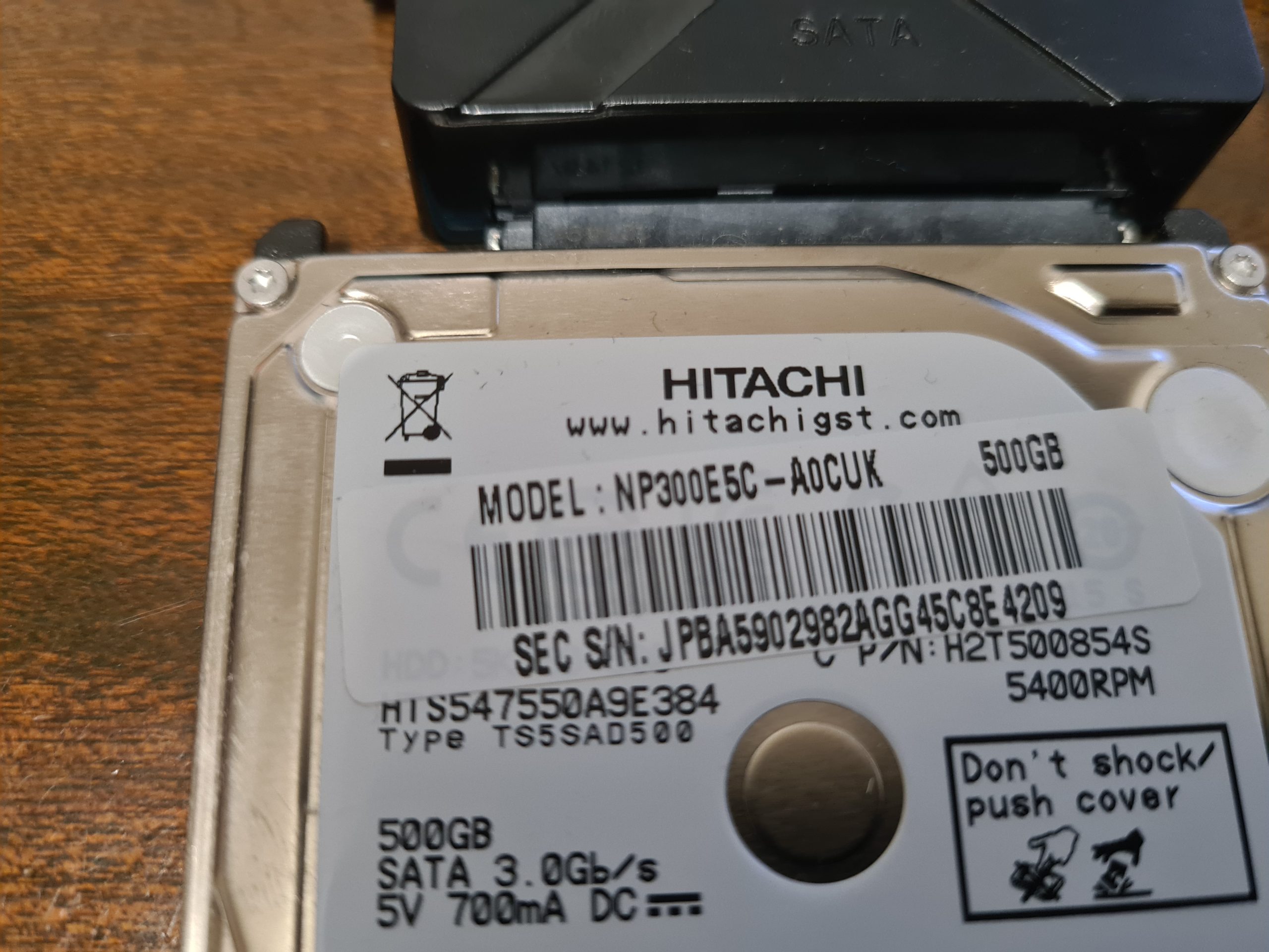
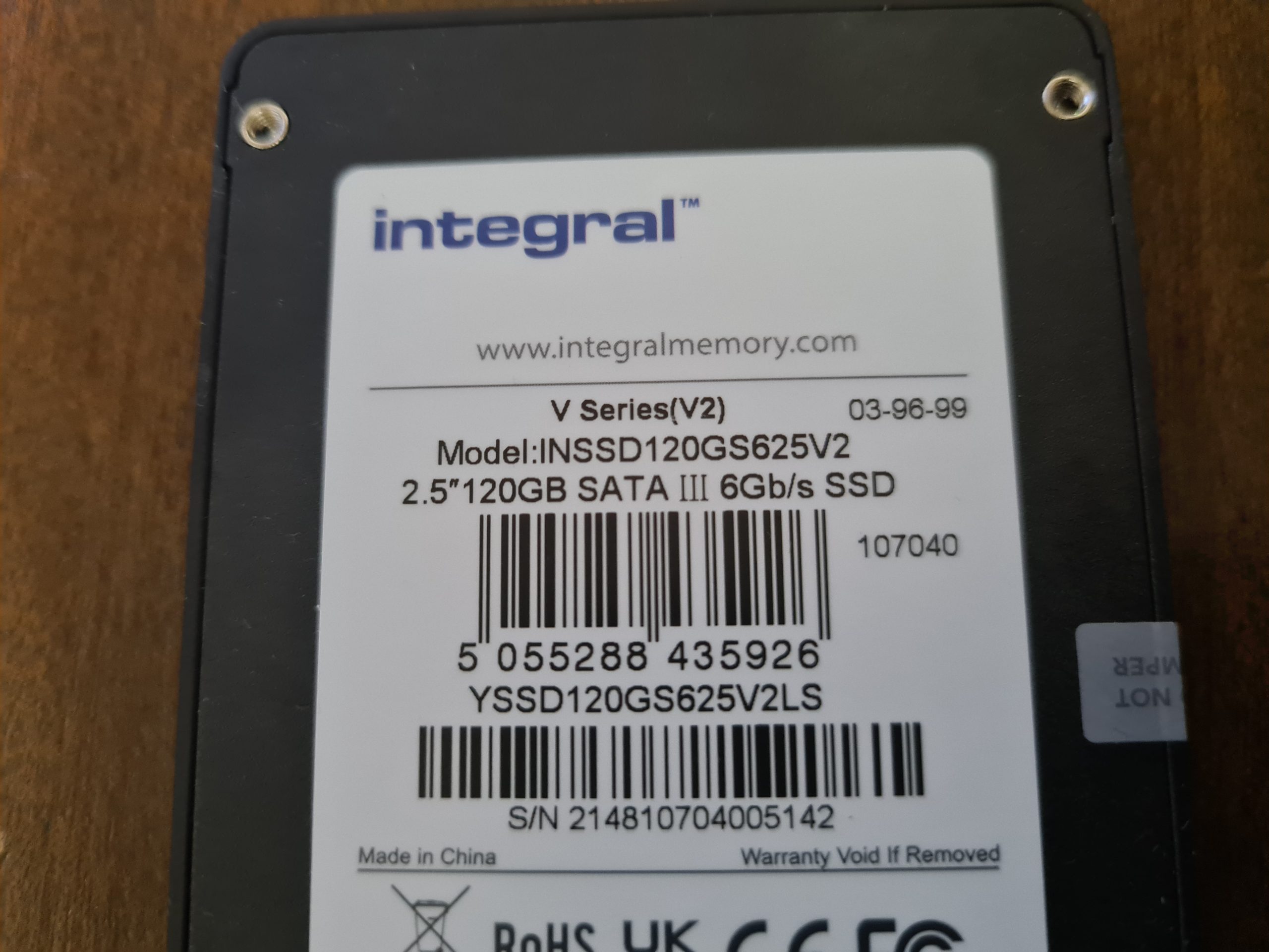
Anyhow, the most important aspect of what I want to mention for this blog post is that all disk drives have a unique identifier. Thankfully this identifier is printed on the physical disk that you have in front of you. It’s printed on the sticker that is physically attached to the disk.
Make a note of the ID of the Disks.
I cannot stress this enough. Make sure you have the IDs of the disks you are working with to transfer data from and to. Make a note of the labels printed on the physical disks so that you can ensure you are transferring data from the right source and to the correct destination.
There is no going back from an incorrect action at this step.
Physical Disks, Partitions and Bootable Disks
Next, before we actually get onto to the migration, it’s important to understand the context. There is a Physical Disk connected to the computer, but then we have Partitions and Boot Partitions to contend with along with both physical and logical volumes. Volumes is just another word for Partition.
This all depends on your specific use case. For example, if the disk you are cloning is from an external USB hard disk, then this probably doesn’t have a bootable operating system setup as it is just there to store basic data. Whereas if you are upgrading your primary disk that runs your operating system, then you will have a Boot Partition which is the part of the disk that runs a piece of software called the Boot Loader which is responsible for booting the operating system you have installed.
For Example;
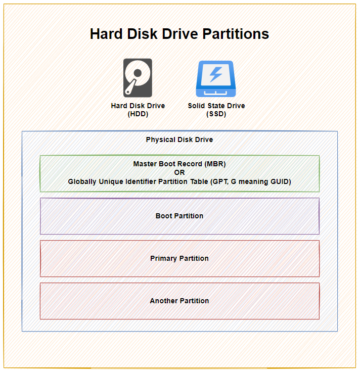
As you can see above, with 1x physical disk drive, whether that is a Hard Disk Drive (HDD) or a Solid State Drive (SSD), they ultimately have the same bits under the hood to make the disk work as it should based on you requirements – either as a Bootable Disk or a Non-Bootable Disk.
To explain a few concepts;
- The Master Boot Record (MBR) was for disks less than 2 TB in size. In reality these days, most disks are larger than 2 TB in size, so as a general rule of thumb, you are probably best always using Globally Unique Identifier Partition Table (GPT) when managing your disks. MBR has a maximum partition capacity of 2 TB, so even if your disk is 10 TB, the maximum size of any one partition is 2 TB, which soon becomes a pain to manage. Compared with GPT which has a maximum partition capacity of 9.4 ZB, so you’re good for a while using this option
- Primary Partition, this is where your operating system is installed and your data saved
- Another Partition, this is just an example where some people use multiple partitions on the disk to manage their data. In reality, for basic disks you are likely only using one primary partition for standard computer use. When you get into the world of Servers and Data Management, then you end up having many logical partitions to segment your data on the disk for the virtual machines using that data, but that’s out of scope of this blog post.
I have seen this a few times in practice when computers have come my way to fix after a ‘professional’ had already apparently fixed something and clearly it wasn’t done correctly. One recent example was with a 3 TB disk drive, yet only 2 TB of it was available for use as it had been configured with only one partition which had a maximum of 2 TB of size. Clearly the person setting this up didn’t really look too closely at anything they were doing, particularly as their primary ‘fix’ was to replace a 3 TB disk drive with a 120 GB disk drive, then the end person using the machine was sat wondering why nothing no-longer worked and the only way they could access their files was from an external USB drive. #FacePalm
Windows Disk Management
So what does all this look like in practice? Well, thankfully Windows 10 comes with a handy utility called Disk Management. To access this, simply right click on the Windows ‘Start Menu’ Icon and click on ‘Disk Management’.
To bring the above conceptual diagram into focus, here is a real example of what this looks like with multiple disks to a computer;
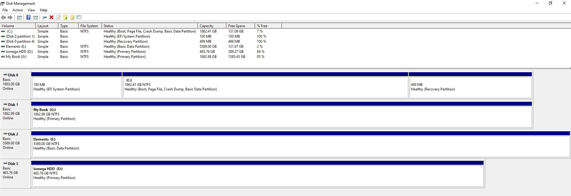
In the above example you can see that there are 4x disks connected to the machine. One is the main disk used for the operating system and the other three are external USB hard drives in this example. What is a tad annoying with this user interface though is that it isn’t clear exactly which disk is which, so you have to be extremely careful. To any user Disk 0, 1, 2, 3 doesn’t really mean anything so at best you have to try and align the disk sizes to what you can see within your ‘This PC’ on your Windows machine.
Thankfully when you Right Click on one of the rows and click on Properties, you can see the name of the disk come up as can be seen below;
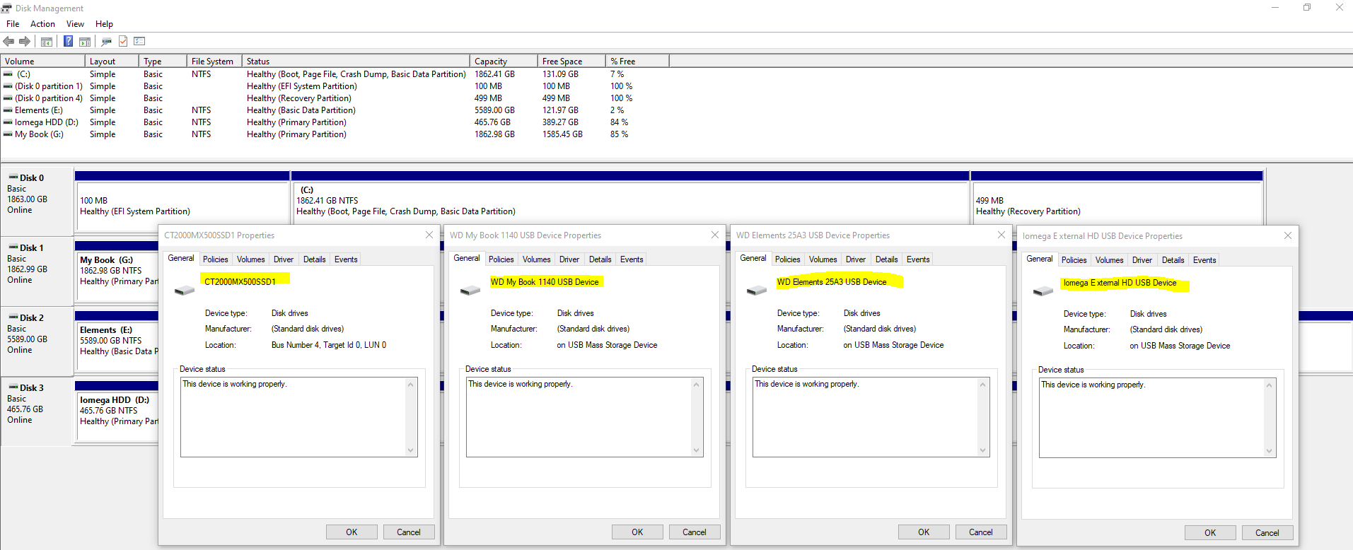
This info will come in extremely handy when you start plugging in some disk drives that you are going to be working with. It’s essential that you are moving data from the correct disk to the correct disk.
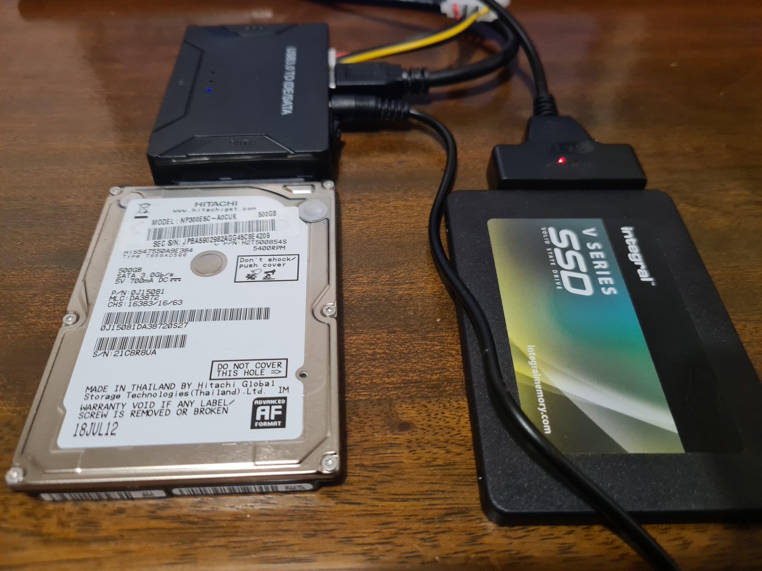
Plugging in Your Disks
Ok, so now we’ve covered off the background topics for how to clone a hard disk, it’s time to jump in and give this a go. You must take this a step at a time to ensure you are 1000% confident that you are sure that you are doing the right thing. As I have said many times already, if you get this bit wrong, it’s going to be very disruptive – particularly if like many people you still don’t have 100% of your data backed up in the cloud.
So, here’s what you’re going to need;
- Old Disk
- New Disk (Contact us if you need us to supply and we can price things up if you aren’t sure what you’re looking for)
- USB External SATA Disk Drive Connector / Adapter Cable (buy here)
- USB External SATA, 3.5” IDE, 2.5” IDE Disk Drive Adapter Tool Kit (buy here)
Make a note of the IDs of your disks from the labels on the physical disk drive. You should see these exact names show up in Windows Disk Management Utility Software. It is these IDs that you will need in the next step to make sure you are cloning the data from and to the correct disks.
One item to note is that if you are using a brand new disk for your New Disk, then you will need to Initialise the disk using GPT via Windows Disk Management Utility Software when prompted once it is plugged in. For disks that you are re-using then this initialisation step usually doesn’t appear. For new disks you will also need to right click on the unallocated area of the disk and select New Simple Volume, then give the Volume (aka. Partition) a size and a Drive Letter then you can format the new partition so you can use it going forwards. Then the drive is ready for use.
Clone Hard Disk Software
There is a small handful of software available both commercially and open source for cloning disk drives, with significantly varying usability aspects. For simplicity, we’re going to take a look at one of the easier to use pieces of software called Acronis True Image for Crucial.
Aconis is a commercial product, but many manufacturers have a free Clone Disk feature within Acronis, such as for Crucial Disk Drives the above software works. There are a lot of makes/models of disks on the market, so if in doubt about what software works best with your hardware, then contact the disk drive manufacturer directly via their support channels and they can advise best which software works best with your hardware.
There are also lots of super technical open source options available, but personally I’ve just not had time to play with these since this is fundamentally a basic copy and paste job fundamentally so it should have a user interface for allow anyone to do this kind of thing in my opinion.
Here are a few images of the setup I was playing with for the purpose of this blog post;
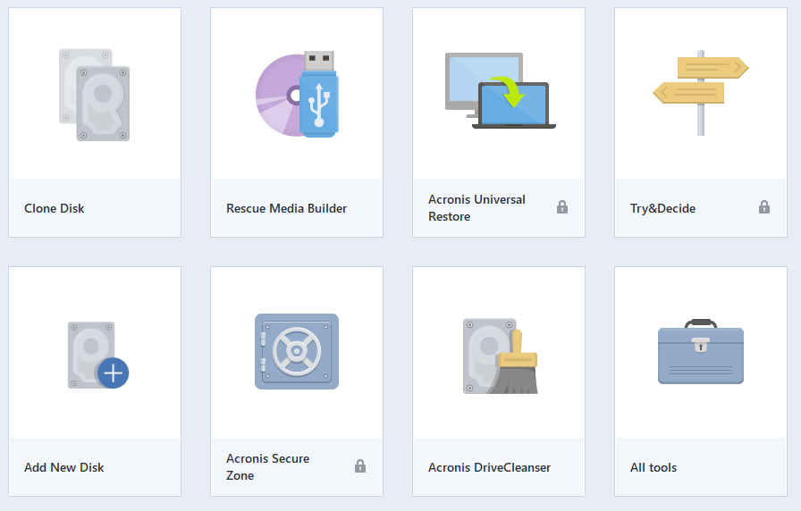
Open Up Clone Disk Tool in Acronis
When you have Acronis open, select the Clone Disk tool. Note, this can take a while to open up, so be patient.
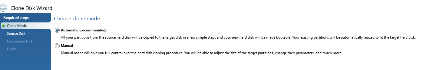
Select Automatic Clone Mode
This is the mode that is most common to use which handles everything in the background for you. The Manual mode gives you much more control but can often be a bit overwhelming if you aren’t too familiar with some of these concepts.
Select Source Disk
This step is particularly important, make sure you select the correct ID that is printed on the hard drive sticker so you are confident you are moving data from the correct disk drive.
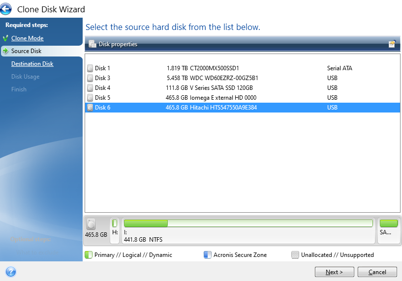
You’ll notice the handy info that Acronis displays at the bottom which shows how the partitions on the drive are currently set up and what is and isn’t being used. This comes in very handy in the next step, particularly as in this case the data is being migrated from a 500 GB HDD to a 120 GB SSD. Your math is correct, that doesn’t fit – but – Acronis is smart enough to only transfer the data that is being used which means that in this scenario the data will fit.
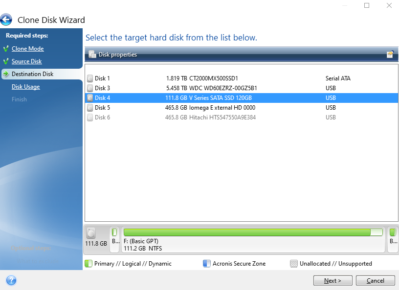
Select Destination Disk
Same as the previous step, make sure you are selecting the correct disk based on the IDs of the disk that is printed on your physical disk.
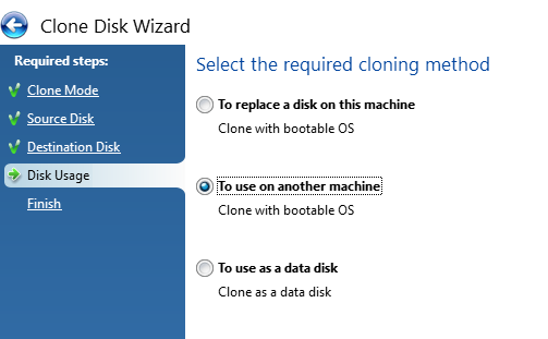
Select the Cloning Method
Next, select the cloning method you are doing. In my case both the old and new disks are connected via USB and are going to be used on another machine, not the machine that Acronis is installed and being run from. Generally speaking, when disk drives start failing, the machine they live in also becomes fairly unresponsive and/or just extremely sluggish. So it’s often easier to whip out the old disk drives and get them plugged into a decent computer that can do the grunt work.
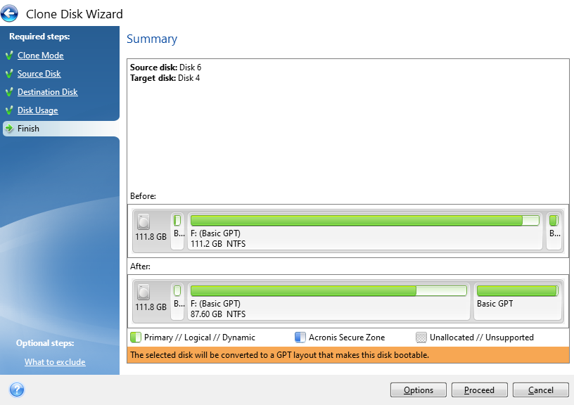
Confirm Settings and Start the Cloning Process
The final step is just confirming what your new disk will look like both at present and after the conversion process. In this example, this is an existing disk that is being flattened and re-purposed which is why the before info shows that the disk is full. If you are using a brand new disk, this will show up mainly empty as there will be nothing on it.
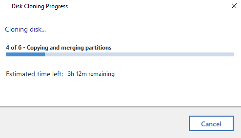
Now it’s just a case of sitting back and waiting. I’ve mentioned already Acronis is a slow piece of software for whatever reason. Just getting to this point probably took around 45 minutes believe it or not. The cloning process takes even longer. So make sure everything has plenty of juice to keep the power on throughout the process or you’ll end up losing a lot of time going through this process again.
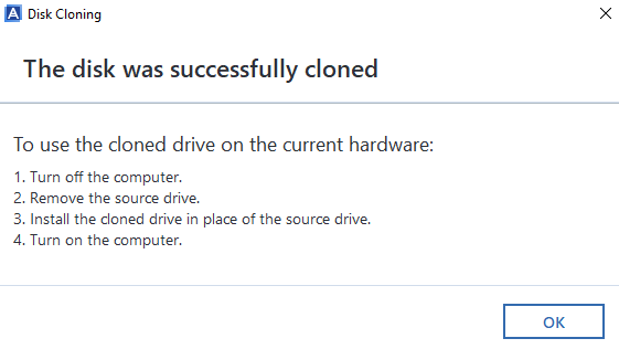
Disk Clone Successful
Woo! Finally, the cloning process has been complete. Now it’s just a case of plugging the new disk drive back into the computer you took the old one out of and everything should be back to normal, working fast again etc. If you do get any problems with this point, then generally the clone will have failed, even though Acronis says that it has worked. i.e. missing a bootable sector or some other form of corruption that is going to be near impossible to get to the bottom of.
Backups, Cloud, Redundancy Etc.
Ok, so we’ve run through the process of cloning hard disks either from HDD to HDD, HDD to SSD or SSD to SSD. Whatever your situation has been. What we haven’t covered off on this blog post yet is around backups, cloud and data redundancy etc. So let’s keep this topic really simple… your hard drives will fail at some point, so plan for it.
Use cloud service providers for storing your data, they have endless backups in place that are handled for you automatically without ever thinking about it. If you only have your data on your main hard disk in your computer, there is a chance that when your disk fails, you will permanently lose your data. Do not go backing up important data to external hard drives, this is manual, error prone and is still likely to result in some data loss for your data when one or more of your hard drives fail.
This is a topic that I could go into for a long time, but will avoid doing so within this blog post. Instead, let’s just keep things simple and ensure your data is backed up to the cloud. And make sure you can easily recover from a failed hard disk and be back up and running within hours, not weeks.
Notes on Failing Disks
Important to note that if you are working with a failing disk, then you can pretty much throw all of the above out of the window. Give it a go, but it’ll probably fail. You are probably best off getting a new disk drive and installing Windows 10 from scratch then you can copy the files over that you need (and backing them up to the cloud!). It’s a bit painful doing this but often it’s the only route when the disk drive has gone past the point of no return and is intermittently failing and doing random things. I’ve seen random things such as monitors flashing on/off with the Windows desktop going blank then back again on a repeat through to disk recovery software failing when it tries to read one single bit of data on the disk, usually about 95% into the process. It’s always best not to get to this point. Some other nuances I’ve seen is that BIOS wasn’t detecting the disk after an apparent successful clone, yet I could see the drive in Windows Device Manager when plugged into another machine, but it wasn’t showing up in Windows Disk Management. All very odd.
When thing get to this point, it’s time to just give up on the old disk, get Windows installed on a brand new one and salvage what you can. Learn your lesson and don’t make the same mistake twice. There are advanced recovery (and costly) options available to do deep dive recovery of data, which again on failing disks can even still be a bit hit and miss so you could be throwing good money after bad trying to recover this data, but it all depends on how important that data is to you.
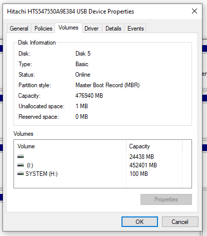
Check What Your Old Disk is Using – GPT or MBR
Something we didn’t go into in too much detail so far but is important to mention. GPT VS MBR – Make sure you check what the old disk is configured as. Or you’ll be repeating the processes again, or be forced to use a commercial bit of software to change GPT to MBR or the other way round. To do this, within Windows Disk Management, simply Right Click on the old drive and select Properties, then click on the Volumes tab where this info will be displayed. In this case we can see that the old drive is using MBR, so it’s best to configure the new disk drive also to use MBR because the computer this came from could (and likely will) have certain limitations at the BIOS layer about if MBR or GPT is supported (aka. UEIF Mode either Enabled or Disabled).
Note, Acronis is a pretty dumb and opinionated piece of software. It assumes that the Destination Disk Partition Mode (MBR VS GPT) is determined purely based on the computer that Acronis is running on. This is dumb, and quite frankly a fundamental flaw in the software in my opinion. In the vast majority of use cases in my experience, the Source Disk and Destination Disk are going to be plugged into an independent computer that is merely there to perform the copy and paste job.
MBR VS GPT is a Legacy VS Modern topic that is beyond the scope of this blog post. But what is important to note beyond the disk drive is that this comes down to the Motherboard’s BIOS Settings in relation to UEIF which is either Enabled or Disabled. Even still, there can be many compatibility issues in this space.
Sometimes, it’s just more effort than it is worth trying to upgrade a computer though. If it’s old, the Old HDD is old, then all the other components are old and slow. Sometimes it’s just more economic to throw away (recycle) the old and get a brand new computer and/or start with a fresh installation of Windows and go from there.
There are many bits of software that can help with cloning disks include: Clonezilla, Macrium Reflect Free, DriveImage XML, SuperDuper and many more. Many come with free basics and trial periods, but generally if you want to do something in full with an easy user experience, then you’re going to be using the commercial offerings.
After personally getting rather frustrated with Acronis, I decided to have a little rant on the Acronis Support Forums. Summary being “Unfortunately this is very unlikely to change for all users of Acronis True Image! This is because Acronis no longer support or develop this product.” And “The MVP community have been asking for this for some years but without any success.”. Not a very positive message, but at least an honest one from a senior member of the community given the lack of engagement from Acronis directly.
Summary
Hopefully this has been a helpful and detailed blog post for how to clone a hard disk drive (HDD) or solid state drive (SSD) and how you can handle this process for either failing disks or just upgrading disks to newer, faster and larger models.
Please take care when performing these actions and if you aren’t sure what you are doing, then leave this to the professionals. There are a lot of nuances with these types of actions which can be extremely destructive if you get this wrong. Be careful.
by Michael Cropper | Sep 26, 2022 | Developer |
There are many ways to skin this cat, so this blog post is going to look at some of the ways that you can help simplify Apache Virtual Host configuration on Linux by breaking things down into manageable self-contained chunks with bounded contexts, aka. all around a domain name which is what 99% of people will be aiming to do.
The difficulty with the official documentation for Apache Virtual Hosts is that it provides many different examples to follow, but gives very little contextual information around use case and instead goes very deep into the art of the possible without guiding you to where you should look. And I guess that’s fine to an extent for official documentation, but it’s also not very useful at the same time as different configurations require different levels of complexity.
So in this blog post we’re going to focus on the common setup for what the majority of use cases for Apache Virtual Hosts are and how you should probably set this up to make your life easy.
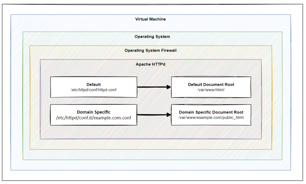
System Architecture
Firstly, it’s important to understand the situation we find ourselves in. Below is a basic hierarchy of layers where this sits. Naturally this is going to differ in reality for most situations, but conceptually in most cases, this tends to be the setup that is ultimately in place in one way or another with a few nuances along the way.
- Virtual Machine
- Operating
- Firewall
- Apache / HTTPd
- Default
- Default Document Root
- Default httpd.conf
- example.com
- example.com Document Root
- example.com httpd.conf
- another-example.com
- another-example.com Document Root
- another-example.com httpd.conf
Operating System Firewall
Keep an eye on this, this is one of the steps that causes a lot of confusion. People often start working at the Apache HTTPd layer, yet haven’t opened the correct ports on the Operating System Firewall. By default many modern operating systems are out of the box configured as a deny-all setup so are likely to block traffic before it’s even reached your Apache HTTPd installation, usually the default open ports are only port 22 for SSH access.
Remember, the layers of your system are essential to understand in detail to make your life easier debugging problems.
The operating system firewall is beyond the scope of this blog post, so we’ll cover this off in a subsequent blog post, but always keep this in mind.
Apache HTTPd Installation
When we install Apache HTTPd via tools such as Yum it will create folders, files and scripts throughout the system. The important ones being;
- /etc/httpd/ – For the configuration aspects of Apache HTTPd
- /var/www/html – For the files that need to be served to users accessing web applications
This is the basics.
For single website hosting this can be more than fine to work with out of the box with zero additional configuration. In reality, most Apache HTTPd installations are hosting many websites, essentially acting as a mini-reverse proxy inside the virtual machine to host multiple websites on the same virtual machine and ultimately the same underlying infrastructure.
Document Roots
Ok, so getting back to basics here. What is a Document Root? In simple terms, this is the home directory for a specific configuration. To put this into context, most people run Windows computers for personal and corporate use. In this example, your “Document Root” is the equivalent of “My Documents”.
So when User 1 logs into a Windows computer they go to “My Documents” and see their own files.
When User 2 logs into a Windows computer they go to “My Documents” and see their own files.
The concept of a Document Root is essentially the under-the-hood configuration that makes this possible.
So in the same way when we are hosting multiple websites this essentially allows us to direct example-one.com to /example-one/index.html, and example-two.com to /example-two/index.html.
Conceptually this is what we’re working with, despite the terminology and underlying configurations being fairly complex using lots of terms that aren’t familiar to 99.9% of us and having to search the web to gather these pieces of information.
So, let’s dig deeper…
Default Document Root – /var/www/html
The default Document Root that is created on Apache HTTPd installation usually lives at /var/www/html. You can confirm this on first installation if you setup Apache HTTPd and then try to access the IP address of the virtual machine. If you have no advanced configuration sitting in the way, you’ll see a successful page that shows a message confirming that Apache HTTPd has been successfully installed. Awesome
Domain Specific Document Root – /var/www/example.com/public_html
But, what if you want to host multiple websites using Apache HTTPd, you need to segment this into a separate Document Root for ease of management. Essentially two separate folders for two different domains;
- example-one.com > /var/www/example-one.com/public_html/index.html
- example-two.com > /var/www/example-two.com/public_html/index.html
Create a basic “Hello World” index.html file for Example One and Example Two so you can easily identify the two and you’re good to go.
You’ll notice that if you check these locations after initial setup that they don’t exist. You need to create these folders and files using Linux commands such as mkdir and nano index.html if you’re not too familiar with these commands. These commands are the equivalent on Windows of right clicking and selecting the Create Folder menu item and the Create File item respectively.
Here we have now created two separate folders, aka. Document Roots, that we can then use to configure the Apache HTTPd Configuration.
Apache HTTPd Configuration Files
Now that we’ve covered off the Document Roots which is where your files live, the next step is to cover off how to configure Apache HTTPd Virtual Hosts properly to ensure your hostnames can root to the correct Document Root.
Default HTTPd.conf – /etc/httpd/conf/httpd.conf
The default configuration file that comes out of the box with Apache HTTPd is located at /etc/httpd/conf/httpd.conf. This is the global single file that rules them all. What is important though is that this file can be added to and also extended or overridden. This is where things get interesting.
There are many way to skin a cat, and this is one example. Fundamentally there are two ways to extend the Apache HTTPd configuration, one of them is by extending this main configuration file. The other is what we’re going to cover off next.
While is it possible to extend the main Apache httpd.conf file, it’s generally bad practice to do so when you are configuring virtual hosts. Mainly because it makes things significantly more difficult to manage and maintain.
If you do want to add Virtual Hosts configuration to the primary httpd.conf file then you simply add these details;
[XML]
ServerName mk1.contrado.cloud
DocumentRoot /var/www/mk1.contrado.cloud/public_html
ErrorLog /etc/httpd/logs/mk1.contrado.cloud-error.log
CustomLog /etc/httpd/logs/mk1.contrado.cloud-access.log combined
[/XML]
Ultimately though, whatever you do in your httpd.conf file, can be over ruled by a separate domain specific configuration file. This is what we’re going to cover next.
It’s not best practice to add Virtual Hosts to your httpd.conf file as it keeps every single configuration bound to a single file which can cause problems with dependencies over time.
Domain Specific HTTPd.conf – /etc/httpd/conf.d/example.com.conf
So we’ve talked previously about adding the specific configuration to a separate Apache HTTPd configuration file which is what we’re going to look at next. Apache is a well-established and advanced piece of software which understands parent/child relationships. And this is the case with .conf files.
As we’ve seen earlier around how the core httpd.conf file is located and how the override is configured, let’s look at this;
- /etc/httpd/conf/httpd.conf – Default Apache HTTPD configuration file
- /etc/httpd/conf.d/example.com.conf – Domain specific Apache HTTPD configuration file
It’s not super complex in practice, while under the hood it clearly is. Ultimately it’s a simple scenario that if there is a domain specific configuration file then this takes priority over the general configuration file.
And all this is managed through the configuration of the Apache HTTPd Virtual Hosts syntax.
To manage this effectively, simply create a file using the command;
nano /etc/httpd/conf.d/example.com.conf
Then add in the exact same configuration details that we’ve outlined earlier;
[XML]
ServerName mk1.contrado.cloud
DocumentRoot /var/www/mk1.contrado.cloud/public_html
ErrorLog /etc/httpd/logs/mk1.contrado.cloud-error.log
CustomLog /etc/httpd/logs/mk1.contrado.cloud-access.log combined
[/XML]
What this essentially means is that Apache will take into account these additional configuration files and use them to override the default. This is all accomplished via the primary http.conf file mentioned earlier with the out of the box configuration of;
IncludeOptional conf.d/*.conf
There is nothing specific to configure to make sure this is working.
Virtual Machine or Apache Level SSL Configuration via Let’s Encrypt
There are many way to ‘do’ SSL. In most legacy on-prem setups, you’ll tend to find that SSL is offloaded at the primary on-prem firewall and traffic is unencrypted from that point forward as traffic travels to the correct virtual machine with Apache or Nginx is running etc.
I’m not saying this is bad practice per say, because it works, but yeah, it’s often a very error prone setup with all eggs in one basket and all and often causes significant bottle necks as the primary firewall tends to be heavily restricted and any change is virtually impossible to make without weeks of discussions, planning, forms and more – for what is ultimately a 5 minute job in most cases to implement.
So, for the purpose of this blog post and to provide a full end to end setup, we’re going to assume that you’re using modern Let’s Encrypt technologies to generate your SSL certificates on the fly for free every few months automatically, from the virtual machine where your application lives.
If you need more information about Let’s Encrypt then we have covered off several blog posts on this topic over the years so search around the site, some of the core ones being;
Why it’s important to mention this is because of the previous setups we’ve gone through.
Security Considerations
We’ve not really covered security considerations for any of the above in this blog post as this is a significantly more in-depth discussion which has many nuances based on every individual setup, governance and controls.
For the purpose of this blog post, this has been to look at how to host multiple websites behind a properly configured Apache HTTPd Virtual Host setup for applications that you own, control and can trust 100%.
Things get significantly more complex for other applications when there are multi-tenancy considerations which is ultimately where software such as cPanel and WHM come into play, but that’s a topic for another time.
Summary
Hopefully this blog post has provided you with some insight on how to configure Apache Virtual Hosts using Document Roots and HTTPd.conf files and separate domain specific HTTPd configuration files to help make your life easy to manage and keep configurations segmented.
As with everything Apache and HTTPd related, everything is going to be specific to your individual use case so please treat this blog post as guidance not a rule. Take a look at your own set up and assess how any of this information may or may not apply to your specific setup.
Hope this helps.
by Michael Cropper | Sep 19, 2022 | Developer |
I’ve found that this topic is quite an undocumented one online and lots of assumptions tend to be made. The majority of content online under this topic that I’ve come across tends to direct you down the route of HA Proxy, which can be fine with very specific setups. But, the minute you want to start to do anything more complex than the basics, HA Proxy soon becomes limiting.
Many websites these days have multiple ports open for specific use cases. Take for example one of the most common web hosting platforms cPanel, this requires many open inbound ports at the firewall layer and in other scenarios we want to give the control to the virtual machine’s operating system the power to decide what ports to allow in without having to configure the firewall every time since they may not have access to the firewall.
We did a blog post recently for How to Setup HA Proxy on pfSense to Host Multiple Websites, which is worth a read to understand the differences for what we are going to cover off here. The core difference here is that with HA Proxy, you have to be explicit when configuring it which ties the settings against a single port, which often is too limiting for many applications.
To get the maximum flexibility you need multiple public IP addresses. This allows you to configure things in any way that you require. So this is what we’re going to cover off in this blog post.
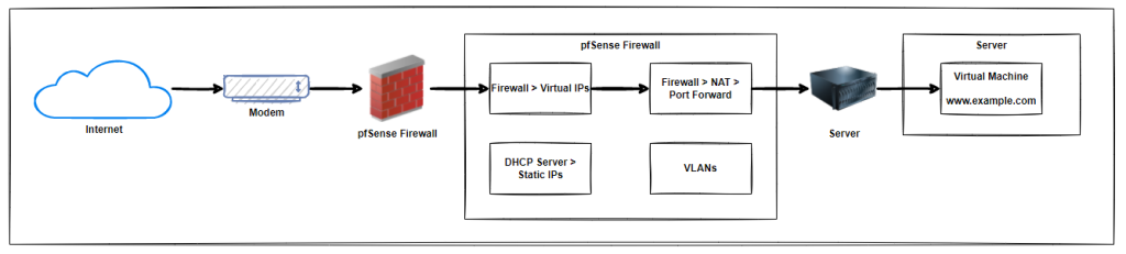
System Architecture
To get a high level view of a setup like this we have the basic components that are outlined below. With a modem, connected to a pfSense firewall which has virtual IP addresses, port forwarding, static IP addresses for virtual machines, VLANs for security configured, then connected to a server with a virtual machine running on it.
In reality, there are often a few bits more along the way and significantly more complex in real world environments, but fundamentally, this is the basic architecture for how all this plugs together.
Purchase Additional Public IP Addresses from your ISP
Firstly, you need to purchase a block of IP addresses from your internet provider. What happens when you do this is that any traffic from those public IP address ranges will ultimately route through to your pfSense firewall so you can then determine what happens to that traffic next.
We’ve covered off a blog post a while ago which helps you to Understand Network Private Address Ranges and looks at the difference between public IP address ranges and private IP address ranges. So take a look at that blog post if you aren’t sure of the difference.
Ok, so now you’ve got your additional public IP addresses.
pfSense Firewall Virtual IP Address Configuration
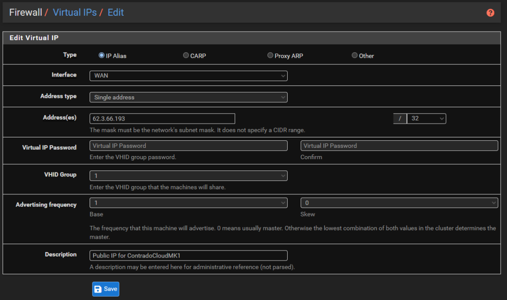
Now it’s time to tell your pfSense firewall about these IP addresses so it knows how to handle the traffic that is coming in. The first step is to setup Virtual IP addresses within pfSense. To do this, simple navigate to Firewall > Virtual IPs.
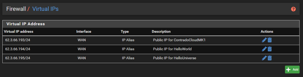
There is nothing particularly complex for settings these up. Simple setup the type as an IP Alias, the interface would be the WAN, the Addresses would be one of the IP addresses with the /32 CIDR range (aka. single IP address), then give it a friendly name and you’re done.
Configure NAT Port Forwarding Rules in pfSense
Now that we’ve got the Virtual IPs configured, it’s time to configure the port forwarding rules so the traffic gets to where it needs to for that public IP address. To get started with this, simply navigate to Firewall > NAT > Port Forward. Then add in some rules.
As you can see in the screenshot below, the settings are rather basic, with the rule being applied to the WAN interface, for the TCP protocol where the Destination Address is the Public IP Address that you added as a Virtual IP Address previously, then forwarding traffic to the static IP address of the virtual machine whenever traffic is received on any port.
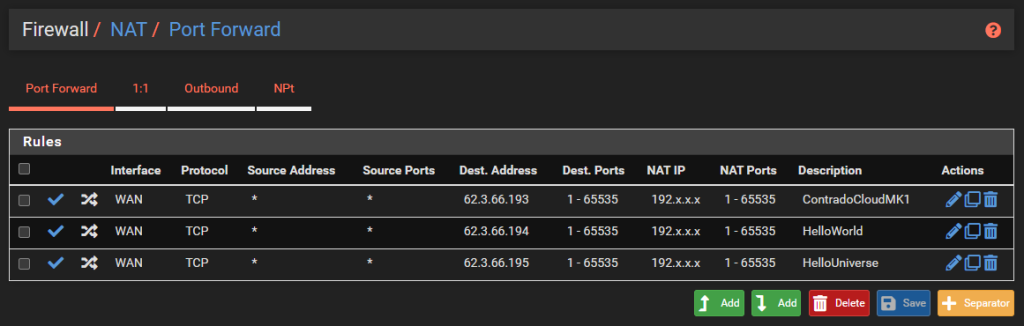
When you do this, pfSense will automatically add a Firewall Rule on the WAN interface.
pfSense Static IPs and VLANs
We’re not going to cover this off within this blog post as this is a separate topic and one that is going to be dependent on your specific setup. The static IP addresses are important to ensure your Virtual Machines always get the same IP address every time they are rebooted so that the firewall rules are still accurate.
Likewise, the VLANs and IP ranges are extremely important from a security perspective to ensure that any inbound traffic is securely segmented from your sensitive internal systems and/or other separate public IP ranges that need to be kept separate from other ones.
Server and Virtual Machines
To keep this bit relatively short and simple, if you have configured all of the above correctly, the traffic that comes into your WAN from specific IP addresses then this will flow through to your virtual machine that you have setup.
So for example, if you have the DNS A Record setup for mk1.contrado.cloud as 62.3.66.193, then this traffic will reach the specific virtual machine where the operating system firewall will then control what traffic it will accept in and what traffic it will deny.
This setup gives you the complete control of the traffic without having to continually play with the pfSense firewall rules.
Summary
Hopefully the above is a handy guide for how to configure pfSense with multiple public IP addresses then use NAT so that you can host multiple websites using multiple ports with minimal configuration within the pfSense firewall.
This is a complex topic, and one that is going to be very different in every single use case. Hopefully this blog post had helped fill in a few gaps in knowledge to get you pointed in the right direction.
by Michael Cropper | Sep 10, 2022 | Developer |
I do this so infrequently, this blog post is mainly as a reminder to myself as a lot of content online around this topic isn’t quite as good as it could be. Anyhow. It’s important to remember how to easily mount a disk in a Linux environment so that it’s possible to control how and where you manage your data storage for your specific use case.
Context and Background
Firstly, understand your own infrastructure you’re working with – in depth. This specific blog post is based on a lab setup to provide guidance, not concrete solutions for production challenges.
The setup in this physical scenario is;
- Type 1 Hypervisor – XCP-ng
- HostOS HDDs/SSDs
- GuestOS HDDs/SSDs
- Virtual Machine running Ubuntu
- Default HDD/SSD Configured
And the scenario that we’re aiming to achieve is an additional disk mount against the ‘Virtual Machine running Ubuntu’. The reason being is that gives us a physically different location to store data against.
In this specific example, we have;
- RAID {X} Array for Type 1 Hypervisor HostOS
- RAID {X} Array for GuestOS Virtual Machines
- RAID {X} Array for Backups
All the above being on the same physical machine.
Partitioning and Formatting
Ensure your disks are partitioned and formatted so they are ready to be used if they are band new. Obviously don’t do this if you have data on the disk that you need. Again, this all comes down to your individual setup, but for ease, make sure your physical disks have been partitioned in the way that you require and have been formatted accordingly.
Attach the Disk to the Virtual Machine
Within XCP-ng Centre, make sure the virtual machine has the disk attached. Interestingly when you do this, this doesn’t mean that it is automatically available to be used interestingly so you can’t navigate to the new disk via the Linux command line, since that is installed on the disk where you installed Linux.
So next, we have to mount the new disk to the Linux installation on the main disk so that it can access that additional storage location.
Find Disk that can be Mounted
Firstly you need to SSH into your Linux virtual machine. To find the available disks, run the command;
fdisk -l
The fdisk utility is designed to manage partitions on hard drives which allows you to create, delete and partition disks for your specific use case. The L flag is for Listing the drives and their partitions. This command is extremely valuable to check if the disk has partitions or not. As you can see below, on the disk in question it has no partitions.
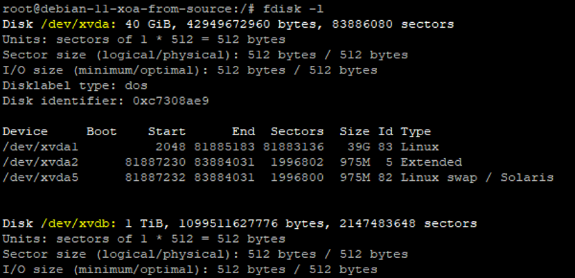
You’ll notice that the top disk in the above screenshot has a lot more information than the second disk which is showing there are no partitions on the disk. So next, we need to get those created.
Create Partition on Disk
As we can see in the previous image, the disk is at /dev/xcdb. So we need to use the fdisk command again to create a partition.
fdisk /dev/xcdb
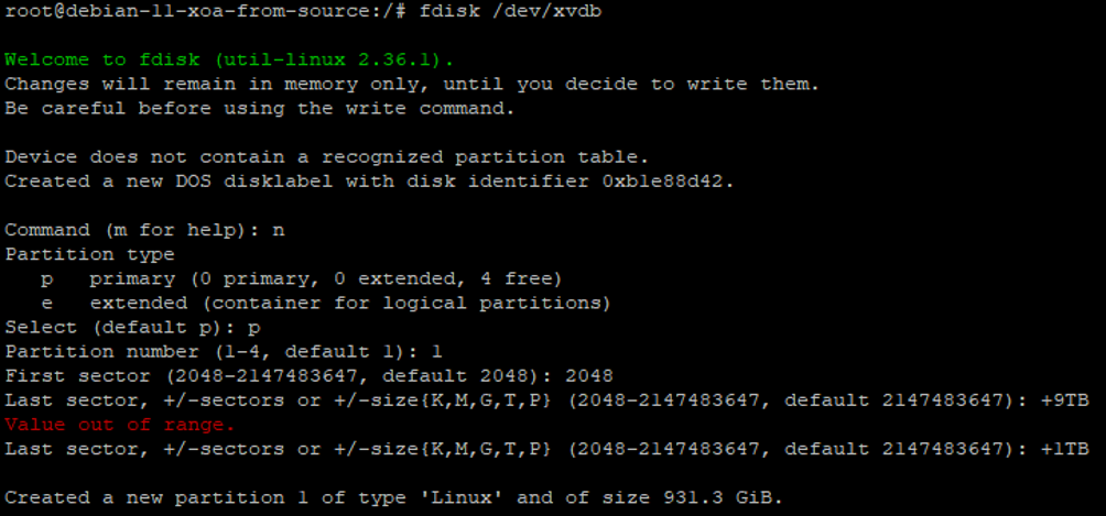
Here we can see we’ve used a couple of commands and configuration options when doing this which are primarily;
- n = New Partition
- p = Primary Partition
- 1 = Partition Number
- +1TB = Size of Partition
After following this through, we’ve now got a partition successfully created.
Next we need to write the changes to the partition table, aka. save changes, so that it is ready to be used with the w command;
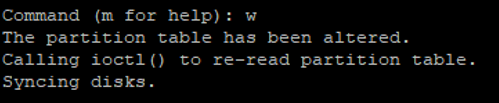
If you run the command fdisk –l again, you’ll see the partition that has been created which is setup as /dev/xvdb1.
Next we need to create the file system using the command;
mkfs .ext4 /dev/xvdb1
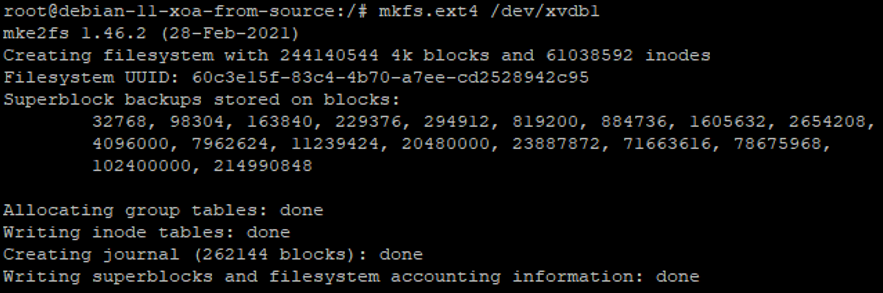
Mount the Disk to Linux
Now we’ve got the disk partitioned and with a file system on, it’s time to mount the disk to Linux so that we can then use it. This part is straight forward now that the ground work has been done to the disk. So run the command;
mount /dev/xvdb1 /mnt/backups
Obviously change the disk name and the location folder to your specific use case.
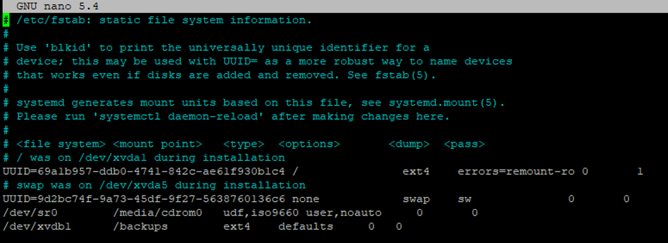
Ensure the Mount Persists after Reboot
Finally, make sure the mount persists on reboot. To do this we use the fstab utility. To configure this, run the command nano /etc/fstab then edit the file as follows;
Save and exit the file. Job done. You can now use that new file system however you want as it is now accessible.